Wafer / substrate process
Where water is usedWater can support production interfaces defined by the approved process.
Why water quality mattersThe quality basis follows the process specification at that use point.
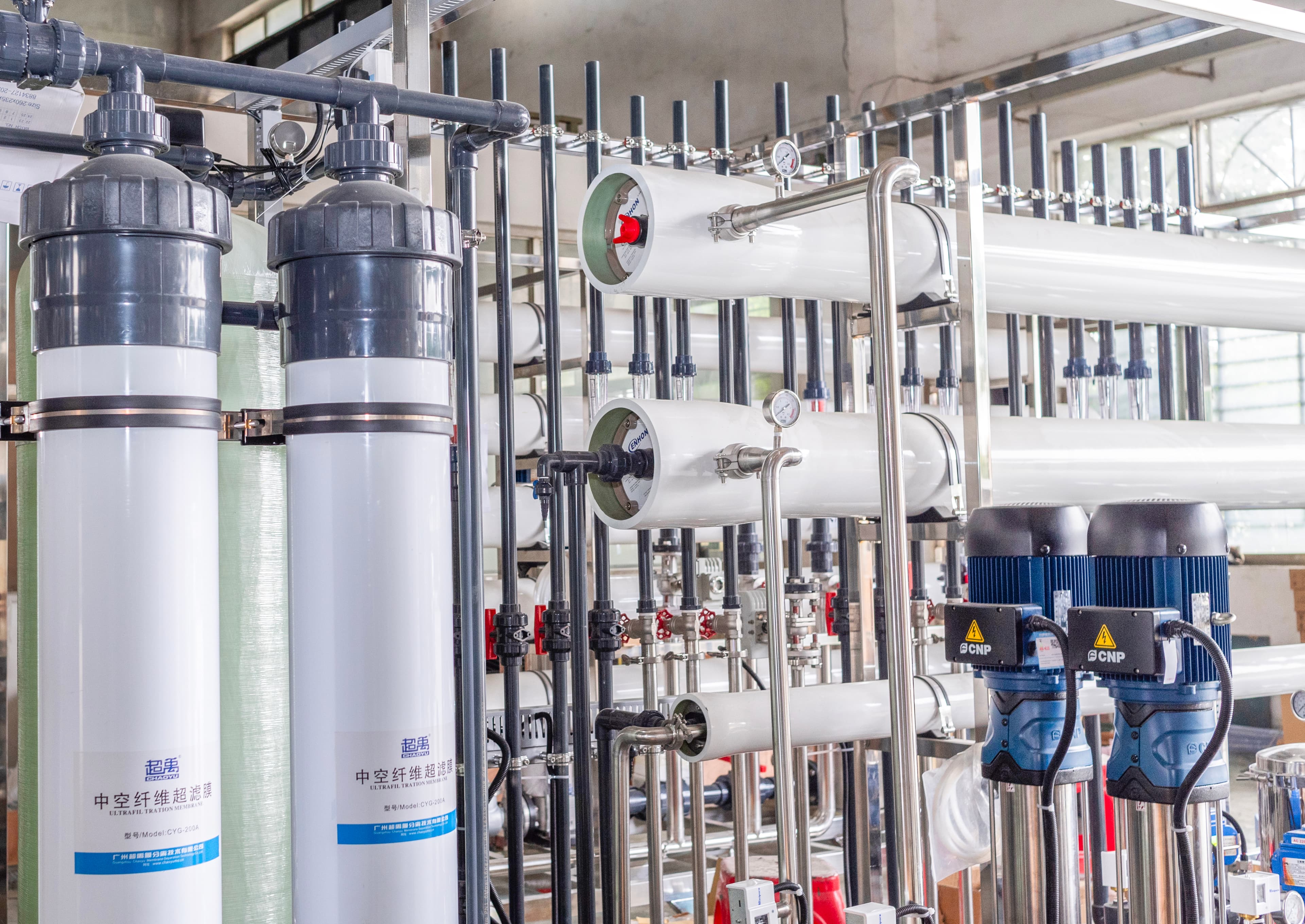
Engineered around contamination control, point-of-use water quality, production demand and distribution requirements—from pretreatment and RO to EDI, polishing and UPW delivery.
Final point-of-use water quality must follow the customer’s process specification. Individual fab use points do not automatically share the same requirement.
Where water is usedWater can support production interfaces defined by the approved process.
Why water quality mattersThe quality basis follows the process specification at that use point.
Where water is usedWet-process utilities may require controlled, continuous delivery.
Why water quality mattersContamination control and demand stability are considered together.
Where water is usedCleaning and rinse points are reviewed independently from general facility water.
Why water quality mattersIons, particles and organics may need different control strategies.
Where water is usedSelected preparation steps can place a higher demand on delivered water consistency.
Why water quality mattersThe final interface, not just generated water, defines the engineering basis.
Where water is usedPost-process duty is mapped with its specific cleaning method and operating pattern.
Why water quality mattersThe treatment and loop must maintain the confirmed delivery condition.
Where water is usedLaboratory and analytical demand can differ from fab process demand.
Why water quality mattersWater quality is set by the actual method, instrument and sampling requirement.
Each control category connects treatment selection, monitoring and the final point of use.
Residual ions can matter in contamination-sensitive production steps.
These indicators help define and monitor the agreed ionic-purity basis.
Organic control may be relevant where the specified production duty requires it.
Particle-control strategy is selected around the final use point and process risk.
Silica review informs upstream and polishing-stage engineering decisions.
Where applicable, control methods and monitoring are set in the approved water-quality plan.
The table establishes the engineering conversation without inventing unapproved numerical limits.
Ionic purity and operating protection
Customer process specification; sampling point and method confirmed during engineering
Organic contamination control
Application-specific requirement and agreed monitoring basis
Residual contaminant management
Feed-water chemistry and confirmed UPW specification
Cleaning and rinse consistency
Use-point risk review and final filtration strategy
Control where relevant to the approved duty
Project-specific water-quality and monitoring plan
Delivery condition and process compatibility
Confirmed by the customer process specification
Point-of-use availability
Normal/peak demand and distribution calculation
Stable delivery at use points
Distribution distance, elevation and interface review
The exact treatment sequence depends on feed-water chemistry and the confirmed UPW specification.
Generation, storage, distribution and the final process interface are one engineering scope.
Where the approved scope requires it, a return loop supports continuous distribution design and water-quality maintenance between generation and point of use.
UPW system sizing is not based only on average flow. Design considers continuous production, peak demand, storage strategy, standby planning and future fab expansion.
Base production-water duty
Short-duration draw at defined use points
Production schedule and recovery planning
Project-defined standby strategy
Demand balancing between generation and production
Modular capacity and distribution allowance
Core UPW generation and selected polishing stages
Explore system 02RO desalination with continuous EDI ionic polishing
Explore system 03EDI polishing within a confirmed UPW treatment train
Explore system 04Pretreatment and membrane-protection stage
Explore system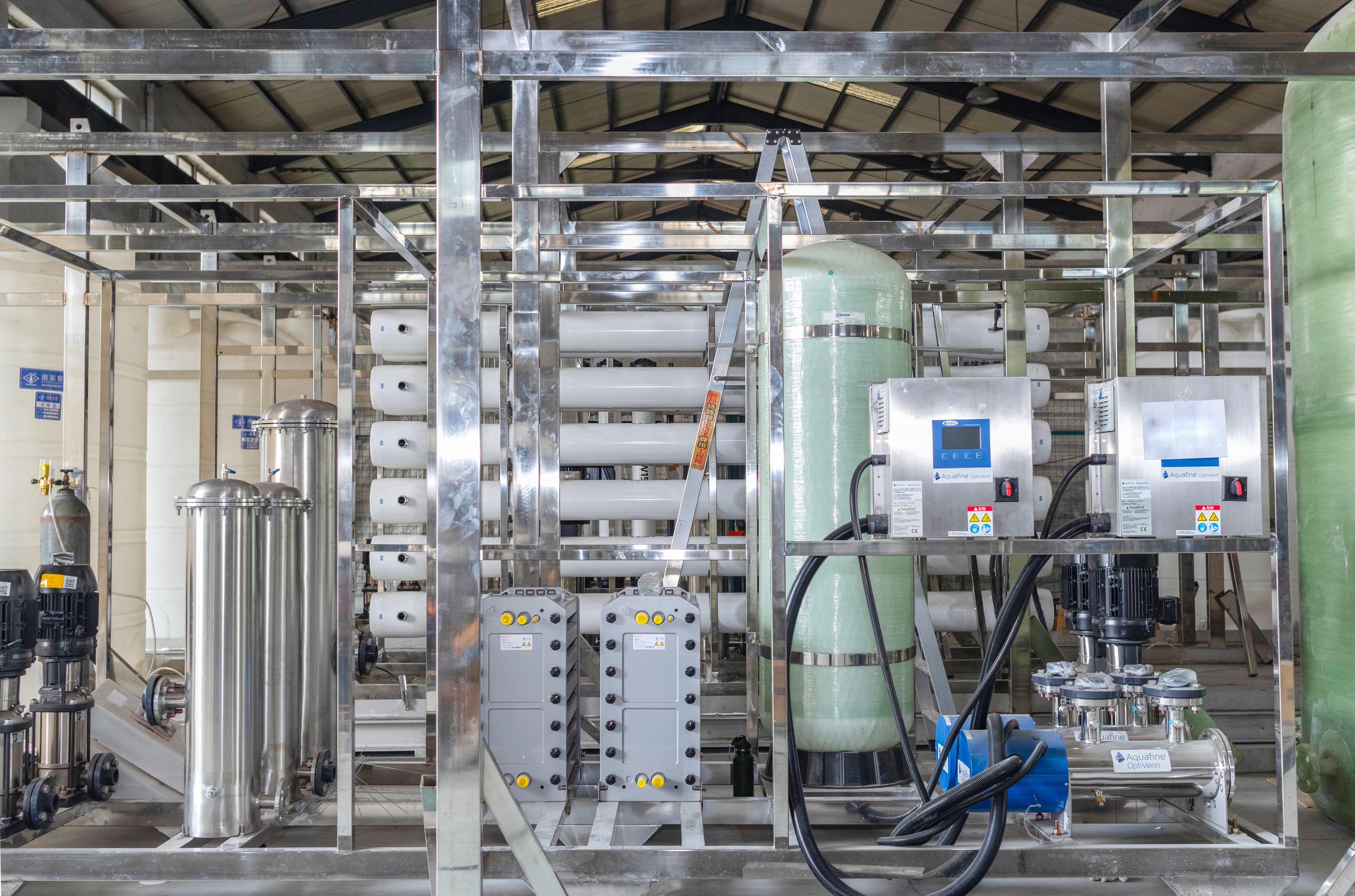
The monitoring scope is configured around generation, storage, delivery and point-of-use interfaces—not supplied as a generic control list.
Final wetted materials are selected according to water-quality requirements and approved project specifications.
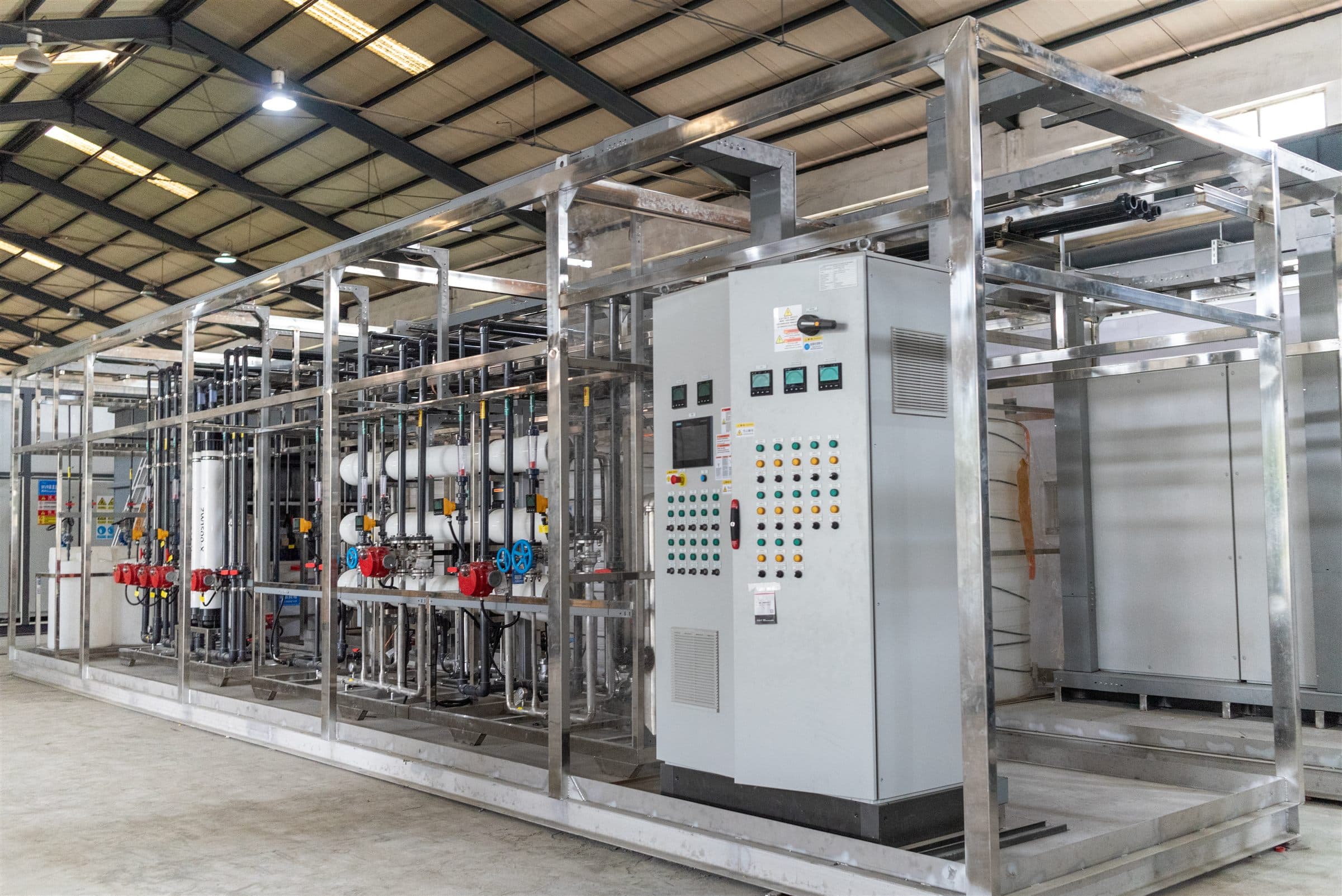
01Configuration review
02Assembly inspection
03Piping inspection
04Electrical inspection
05PLC / HMI function
06Instrumentation review
07Agreed FAT scope
Final FAT scope and acceptance criteria are confirmed in the approved project documentation.These inputs establish the generation and distribution basis before a technical proposal.
Semiconductor manufacturing commonly needs a staged UPW system that can combine pretreatment, RO, second-pass RO, EDI, polishing, final filtration and a recirculating distribution loop. The exact route follows feed-water chemistry and the process specification.
Contamination-sensitive production steps can require controlled water at the point of use. The quality basis is defined by the customer’s process specification, not a generic industry value.
RO is a core desalination stage, but RO alone may not satisfy a confirmed UPW duty. Additional polishing stages are selected only when required.
EDI can continuously polish suitable RO permeate for tighter ionic-control requirements. It is one stage in a connected UPW system, not a substitute for correct upstream treatment.
The relevant parameters can include resistivity or conductivity, TOC, silica, particles, microbiology, temperature, flow and pressure. Their targets and sampling method must be confirmed for each application.
Where required, recirculation helps manage delivery conditions between generation, storage and use points. The loop configuration follows the approved distribution and quality-maintenance scope.
Sizing considers normal and peak demand, operating hours, storage strategy, distribution distance, redundancy and planned expansion—not average flow alone.
Provide feed-water analysis, the UPW specification, demand profile, point-of-use map, distribution distance, utilities, electrical standard, redundancy requirements, location and project timeline.
Expansion can be addressed through modular treatment configuration, reserved plant interfaces, storage strategy and distribution allowance in the approved project scope.
The agreed FAT can include configuration, assembly, piping, electrical, PLC/HMI and instrumentation review. Final acceptance criteria are confirmed in the approved project documentation.
Send your feed-water analysis, UPW specification, production demand, point-of-use map and distribution requirements. We will review the route before recommending equipment.