An RO clean-in-place skid should be specified around the membrane stages it will clean, rather than the plant's nominal permeate capacity. Define the approved cleaning flow and pressure envelope, usable solution inventory, chemical compatibility, connection arrangement and waste route before comparing quotations. Cleaning chemistry and operating limits must follow the installed membrane manufacturer's current instructions.
Separate cleaning duty from production duty
A reverse osmosis production pump and a membrane cleaning pump perform different jobs. Production operation creates the pressure needed to separate water across the membrane. Cleaning operation circulates an approved solution through the feed channels to contact deposits and carry released material away. A quotation based only on production capacity can therefore miss the actual cleaning flow, return pressure and usable solution volume. Start the specification with the membrane model, vessel arrangement, number of elements per vessel and the stage or group that will be cleaned together.
Draw the cleaning boundary on the process diagram. Identify which feed, concentrate and permeate lines must be isolated, which valves establish the return path and where rinse water leaves the system. For a plant with several trains, decide whether one shared skid can reach every connection without unsafe hose routing. Sharing equipment can reduce installed hardware, but it also creates scheduling, cross-contamination and cleaning availability questions. The purchase decision should include the time needed to connect, isolate, rinse and restore each train, rather than only the pump rating.
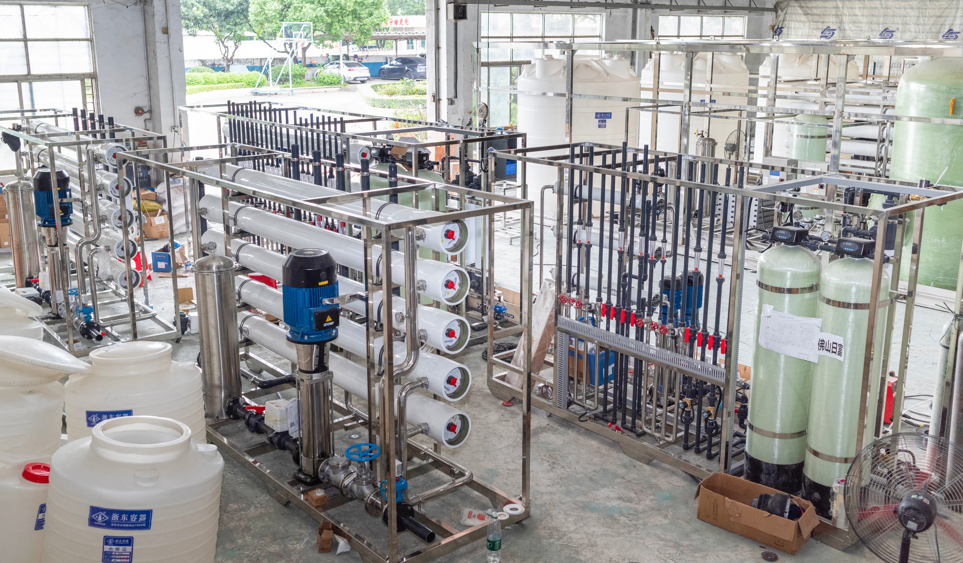
Build the cleaning flow and pump duty from the selected stage
Obtain the membrane supplier's approved cleaning flow range and pressure limits for the installed elements. Translate the required flow per vessel into the total flow for the vessels being cleaned simultaneously. Then calculate losses through the supply pipe, hoses, valves, filter, membrane stage and return line at that flow. Request the proposed pump curve and identify its operating point for each cleaning arrangement. A pump that satisfies the largest stage may need speed control or an approved bypass arrangement when cleaning a smaller group.
The pressure review should protect the elements and their mechanical arrangement as well as the pump. Verify the permitted cleaning direction, concentrate return backpressure and permeate-side arrangement against the element and vessel instructions. Do not assume that reversing the flow will improve cleaning. Include a readable flow indicator, pressure instruments and accessible sampling points in the scope. An operator should be able to confirm circulation conditions without opening a pressurized connection. If the skid will serve different membrane models, document separate operating recipes and prevent an unsuitable recipe from being selected accidentally.
Send the feed-water analysis, target quality, required capacity and operating profile. We will help structure the next engineering questions.
Send your project inputsSpecify usable tank inventory and a compatible heater
Tank volume should cover the liquid held in the connected cleaning circuit plus the working inventory needed to keep the pump suction flooded. The circuit includes vessels, piping, hoses, filter housings and return connections. Gross tank capacity is not the same as usable cleaning volume: low-level protection, freeboard, residual heel and expansion allowance change the available amount. Ask the supplier to provide a volume balance and show normal, minimum and maximum operating levels. Also define how the operator measures water addition and chemical concentration reproducibly.
Heating may be required by the approved cleaning procedure, but the membrane's permitted temperature depends on its type and the solution conditions. Specify temperature indication, independent overtemperature protection and heater shutdown on low liquid level. Review heater surface compatibility and the possibility of localized overheating where circulation is poor. A removable heater or an accessible heat exchanger may simplify maintenance, depending on the arrangement. The quotation should state the assumed starting temperature and available electrical supply. Heating time is a project calculation, not a universal performance claim for every cleaning skid.
Review wetted materials, filtration and physical connections
List the intended cleaning chemicals and their approved concentration, temperature and exposure conditions before accepting a material schedule. Review the tank, pump, piping, seals, valve seats, hose liners, gaskets and instrument connections together. A compatible tank does not make an incompatible pump seal acceptable. The skid should have a filter arrangement suited to capturing released particles during circulation, with an accessible housing and a way to identify restriction. Specify replacement cartridge availability and a safe method for draining the housing before opening it.
Connection details often determine whether the equipment can be used reliably. Request a connection schedule with sizes, fittings, hose lengths, pressure ratings and identification labels. Include caps or closures that protect clean fittings during storage. Plan supports so hoses cannot load small instrument nozzles or obstruct an access route. If connections are permanent, review isolation and cross-connection risks; if temporary, document the connection check before operation. Provide a drainable arrangement where practical and identify trapped pockets that require a deliberate drain step. The final layout should allow inspection of leaks and routine access to wearing parts.
Choose cleaning steps from evidence about the deposit
Before cleaning, review normalized operating trends, differential pressure, feed-water changes and previous cleaning records. Low production flow by itself does not identify the deposit because temperature, pressure and feed composition also affect membrane output. Sampling, deposit analysis or a qualified membrane assessment may be needed where the cause remains uncertain. Select chemistry and sequence from the installed element manufacturer's guidance and the observed fouling mechanism. Avoid treating every pressure increase as mineral scale or assuming that stronger chemicals will restore damaged elements.
The operating procedure should describe solution preparation, initial displacement, circulation, any approved soak, draining, intermediate rinses and return to service. Record actual flow, pressure, temperature and solution condition during the work. Dissolve and mix chemicals before exposing the membrane to the solution, and respect the manufacturer's combined temperature and pH limits. After cleaning, flush with suitable water and divert product water until the applicable restart and quality requirements are satisfied. A cleaning event is complete when the system has been safely restored and its operating evidence reviewed, rather than when the circulation timer expires.
Include isolation, operator protection and the waste interface
Write the valve lineup and isolation method before the skid arrives. The cleaning circuit must not send chemicals into a production storage tank, another operating train or a downstream polishing module. Review electrical isolation, pump dry-running protection, tank overflow and loss of return flow. Controls should make the active cleaning mode visible and require an intentional transition back to production. Provide an accessible stop function and clear instructions for responding to a leak or instrument failure. Personnel protection and chemical handling arrangements must match the actual chemicals selected for the job.
The waste route needs equal attention. Spent cleaning solution can contain removed deposits as well as the original cleaning chemicals, so its suitability for a site drain cannot be inferred from appearance. Define collection, characterization and treatment responsibilities with the facility team. If separate solutions or incompatible wastes must remain segregated, provide identified containers or drain routes. The skid supplier should state which discharge connections are included and which treatment equipment lies outside the supply scope. Confirm access to the relevant chemical safety information and site-approved disposal procedure before conducting a wet cleaning demonstration.
Write an RFQ that can be accepted objectively
A useful RFQ includes the membrane arrangement, intended cleaning groups, approved cleaning envelope, circuit inventory, utility data, connection schedule, materials and control requirements. Ask each bidder to return a duty matrix covering every train and cleaning mode. Require marked drawings, a pump curve, instrument list, spare-parts list and an operating procedure. State whether the factory inspection will demonstrate flow through a representative hydraulic loop or only verify assembly and controls. Where the factory loop differs from the final installation, record the limitation and identify the site test needed to close it.
Agree how acceptance will be documented. Flow and pressure indications, low-level shutdown, heater protection, valve identification, drainage and leak checks can be tested against defined criteria. Membrane performance recovery depends on the deposit and element condition and should not be promised merely because a new CIP skid is supplied. Send Baihuipu the membrane datasheets, stage arrangement, proposed cleaning chemicals and site connection constraints to develop a focused maintenance-equipment brief. A clear cleaning scope makes quotations comparable and gives operators a practical basis for commissioning and subsequent use.
Questions buyers commonly ask
Can one CIP skid clean several RO trains?+
Yes, if its hydraulic range, usable tank inventory, material compatibility and connections suit every intended cleaning group. Review scheduling and cross-contamination controls before sharing it.
Should the cleaning pump match the RO production pump?+
No. Select the cleaning pump from the approved circulation flow and circuit losses, while keeping pressure within the installed membrane and vessel limits.
Does a larger cleaning tank guarantee better cleaning?+
No. Sufficient usable solution volume is necessary, but deposit identification, compatible chemistry, controlled circulation and a verified restart determine the cleaning result.
What evidence should be collected after membrane cleaning?+
Record the actual procedure, solution conditions, rinse and restart checks, then compare normalized membrane performance with the pre-cleaning baseline under comparable operating conditions.
Turn the guide into a project brief.
Final process selection and performance commitments should follow the complete feed-water analysis, application requirements, site utilities and approved technical agreement.