An isobaric pressure exchanger is part of a connected SWRO hydraulic system. Its procurement should define matched flow, mixing, pressure losses and booster-pump interfaces, while keeping device efficiency separate from the total energy consumption of the operating plant.
Define the SWRO operating cases first
Provide feed-water composition, temperature range, product duty and the proposed membrane operating states. Include startup, reduced load, train isolation and seasonal conditions. State the high-pressure concentrate flow and pressure available to the recovery device for each case. An energy-recovery component should be selected against that envelope rather than a single full-load flow taken from an early membrane projection.
Identify the offered technology explicitly. Isobaric pressure exchange transfers pressure energy between streams through a particular device arrangement; it is not interchangeable with every turbine or hydraulic recovery option. Energy Recovery's high-pressure PX description includes packages combining devices and booster pumps, illustrating the integration boundary. Use the actual offered manufacturer's documentation and calculations rather than assigning one branded device's published characteristics to an alternative without supporting evidence.
Draw all pressure-exchanger connections
Mark high-pressure concentrate, depressurized concentrate, low-pressure feed and pressurized feed connections with flow directions and operating conditions. Show where the pressurized feed rejoins the membrane-feed path and where any booster pump operates. Include isolation and instrument locations. A simplified box labelled energy recovery can conceal important pressure and flow relationships that determine the duty of adjacent pumps and valves.
Request a consistent hydraulic balance across the complete train. Identify which losses occur in the device, connecting piping, valves and booster path. Show how the control philosophy maintains the intended flow relationship as membrane conditions change. If several devices operate in an array, explain distribution and isolation. The buyer should be able to follow both water and pressure through the offered package without reconstructing the supplier's assumptions from separate disconnected equipment schedules.
Send the feed-water analysis, target quality, required capacity and operating profile. We will help structure the next engineering questions.
Send your project inputsReview flow matching and mixing assumptions
Ask the supplier to state the required relationship between the device's high- and low-pressure stream flows and how it is measured or controlled. Determine allowable operating limits and the consequence of imbalance. Do not assume that any two nominal flows printed on a membrane report provide adequate integration. Include measurement uncertainty and the practical adjustment available to commissioning staff. A theoretical matched condition needs an achievable installed method of setting and observing it.
Request the offered mixing or salinity-transfer assumptions and show their effect on membrane-feed composition. Device efficiency and mixing are different descriptions. A favourable pressure-transfer figure should not obscure additional salt load or another consequence included in the actual design. Compare bidders on the same definitions and operating cases. Where a calculation depends on manufacturer-specific behaviour, retain its source and limit rather than using it as a universal value for all isobaric equipment.
Coordinate the booster and high-pressure pumps
Define the booster-pump duty from the actual pressure difference and losses in its path. Include suction conditions, operating range and any required control method. Clarify whether the booster is supplied as part of the recovery package or by another vendor. A package boundary that leaves both vendors assuming the other owns flow control can create a difficult commissioning interface even when each individual pump meets its own schedule.
Review the high-pressure pump's role with the recovery device operating and unavailable. Determine whether bypass operation is feasible and what product duty and power demand it would permit. Do not assume that the same plant capacity remains available without energy recovery. Include pump and motor limits in the assessment. The operator needs an explicit degraded operating state rather than a bypass valve that can be opened without understanding its effect on the hydraulic balance.
Specify energy comparison on a common boundary
Separate component efficiency from total plant specific energy. A plant comparison should state which pumps, pretreatment, auxiliaries and product-water conditions are included. Use the same feed, temperature, recovery and product duty when comparing alternatives. Identify whether a quoted value is a design calculation, a manufacturer component result or a site measurement. Those evidence types should not be presented as if they establish the same outcome.
Include off-design operation and the time the plant spends in each important state if an annual estimate is required. State tariff and availability assumptions in any economic analysis and keep them reviewable. Avoid copying a headline energy-saving percentage into another project's purchase specification. The engineering objective is a demonstrable hydraulic and energy balance under defined conditions, with any expected benefit supported by the actual proposed equipment and operating profile.
Review materials, cleanliness and transient states
Obtain wetted materials and compatibility information for the actual seawater and cleaning exposures. Include solids limits and any upstream filtration requirements identified by the device supplier. Request the approved startup, flushing and shutdown sequence. An energy-recovery device can have different requirements from the membrane elements, so the integrator must reconcile their instructions rather than assuming that one generic SWRO sequence automatically satisfies every component.
Assess pressure changes and valve actions with the project's transient review. Show how the device and adjacent pumps are protected during trips and restart. Include stopped-flow, reverse-flow or other states identified as relevant by the offered manufacturer. Where an additional protective device is proposed, define its duty and test method. Keep design limits specific to the component and operating envelope instead of inferring tolerance from the fact that it normally handles high pressure.
Make instrumentation and service practical
Specify the measurements needed to set and verify the operating balance, including suitable flows and pressures at defined locations. Include calibration and commissioning access. A device whose adjustment depends on readings that are not installed cannot be commissioned against the proposed design basis. Record normal settings and ranges after acceptance so operators can recognize an emerging imbalance rather than treating a rise in total pump power as an unexplained seasonal effect.
Review device removal, lifting, clearances and spare-part requirements with the installed array layout. Ask which service tasks require a train shutdown and how multiple devices are isolated where the offered design permits it. Include supplier support for initial balancing and operator training. The quotation should explain maintainability and the consequence of one component being unavailable, allowing the purchaser to compare continuity and installed scope alongside the initial component price.
Agree acceptance and prepare the RFQ
Send Baihuipu the SWRO operating cases, membrane projections, feed envelope, hydraulic diagram and common energy-comparison boundary. Request a coordinated offer for recovery devices, booster interfaces, instruments, valves and commissioning. Agree tests for flow balance, pressure conditions, mixing assumptions where verifiable, protective sequences and the stated operating range. Retain calculations for conditions not reproduced at site and distinguish those from witnessed measurements in the final acceptance record.
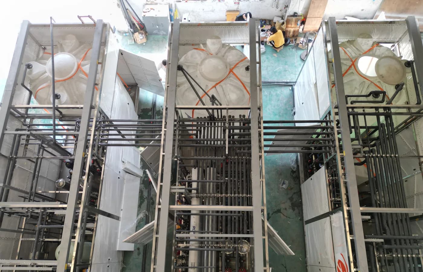
The featured photograph shows an industrial RO treatment train under factory assembly as context; it does not identify a pressure exchanger or prove energy performance. Use the actual offered device documentation and installed test records for those decisions. The related SWRO and pump guides address adjacent boundaries. A complete procurement package joins them through a consistent flow and pressure balance, allowing the buyer to assess energy recovery without relying on an unsupported plant-wide savings claim.
Questions buyers commonly ask
Is pressure-exchanger efficiency the same as total SWRO energy use?+
No. Define the whole energy boundary and operating conditions. Component efficiency alone does not establish the consumption of pumps, pretreatment and auxiliaries.
Why state flow-matching requirements explicitly?+
The installed streams must remain within the offered device's operating relationship. Provide measurements, controls and a practical commissioning method.
Can the booster pump be specified independently?+
Coordinate its pressure difference, losses and control with the exchanger and membrane-feed system. Make supplier ownership of the interface explicit.
Does an energy-recovery bypass preserve full plant capacity?+
Do not assume it. Evaluate pump, motor and hydraulic limits and define the actual approved operating state without the device.
Turn the guide into a project brief.
Final process selection and performance commitments should follow the complete feed-water analysis, application requirements, site utilities and approved technical agreement.