A water treatment flowmeter should be selected from the liquid, operating range and installation conditions at its actual measuring point. Matching the pipe connection alone is insufficient. An effective specification links the measuring principle, hydraulic arrangement, signal quality and acceptance evidence to the operating decision the instrument must support.
Identify the decision served by each flow measurement
Create an instrument schedule that distinguishes production indication, recovery calculation, chemical ratio control and transferred-volume accounting. These uses do not necessarily need the same response, uncertainty or totalizer behaviour. Mark each measurement boundary on the process diagram and identify who uses the value. A feed meter before a recycle connection and another after it measure different duties even when both are casually described as the RO feed flow.
List the normal, minimum and maximum operating cases, including startup, flushing and standby where relevant. State whether flow can reverse and whether the pipe can drain. Identify the consequence of a missing or misleading reading: an incorrect production total is a different problem from dosing chemicals without reliable water flow. This consequence should guide the verification scope and control response, with the responsible process engineer approving the intended function before the instrument is purchased.
Select a principle from water properties and pipe conditions
Compare available measuring principles against the actual liquid. Electromagnetic meters rely on a sufficiently conductive liquid and an appropriate full-pipe installation. Ultrasonic and Coriolis instruments offer different measurement mechanisms, but their suitability still depends on the fluid and installation. Endress+Hauser presents these as distinct technology families rather than interchangeable pipe accessories. Obtain written suitability for low-conductivity permeate, solids-bearing reuse water or gas-containing streams from the selected instrument supplier.
For each candidate, request the minimum applicable conductivity or other fluid restrictions, pressure and temperature ratings, wetted materials and relevant maintenance requirements. Avoid applying a general conductivity threshold to every electromagnetic design. Ask how entrained gas, deposits, solids and changing fluid properties affect the proposed instrument. Record any required upstream treatment or installation condition as part of the purchase specification so that the instrument is not later blamed for a condition outside its stated operating envelope.
Send the feed-water analysis, target quality, required capacity and operating profile. We will help structure the next engineering questions.
Send your project inputsCheck useful range and uncertainty at real operating points
Give bidders actual flow cases and require an uncertainty statement for those points. Distinguish a percentage of reading from a percentage of full scale, and ask whether a low-flow cutoff affects the minimum case. A large turndown statement does not establish useful accuracy throughout the factory operating range. Compare the measurement uncertainty with the decision being made, particularly when a small difference between two large flows is used to calculate another stream.
For recovery calculations, confirm that the meters describe the same time period and boundary. The relationship between permeate flow and feed flow is only meaningful when both values represent synchronized operating conditions. Flushing, recycle and intermittent diversion can disturb that relationship. Ask the controls engineer how totals and instantaneous values are aligned and how invalid data is excluded. This review may reveal a need to move a measuring point rather than buy a nominally more precise transmitter.
Make the installation drawing part of the instrument scope
Show orientation, pipe filling conditions, upstream disturbances, downstream valves and service access on the piping drawing. Obtain the selected model's installation requirements rather than copying a generic straight-length rule. Some designs have different approved arrangements, and space-constrained skids need explicit confirmation. Identify venting or drainage conditions that can leave the sensor partly full. For electromagnetic instruments, resolve grounding and potential equalization using the manufacturer's instructions and the actual pipe material.
Check mechanical supports, flange alignment, gasket selection and any restriction on liner handling. The instrument should not become a convenient structural support for poorly aligned piping. Reserve access for removing the sensor or electronics without dismantling unrelated equipment. Where a bypass is proposed, define its permitted operating use and how unmetered flow is identified. A bypass that improves maintenance access can also invalidate volume accounting unless the control and operating procedures recognize its state.
Specify signals, units and totalizer ownership
Write a signal schedule that identifies engineering units, range, update behaviour and communication method. Ensure the local display, PLC, historian and supervisory screen use consistent units and scaling. Confirm the meaning of zero, below-range, reverse-flow and fault outputs. A communication value that freezes at its last good reading should not silently be treated as fresh evidence that water is flowing. Include instrument status with the measured value where the available interface supports it.
Assign ownership of production totals. Decide whether the authoritative total is held in the meter, PLC or another system, and document reset permissions, power-loss retention and rollover behaviour. If a pulse output is used, confirm pulse weighting and the receiving input's capability at maximum flow. If digital values are used, review data type and timestamp handling. Test these interfaces with a known change in total, since a correct instantaneous display does not prove a correct daily production report.
Distinguish calibration from installed functional verification
Request calibration evidence that identifies the supplied instrument, calibration conditions, results and traceability. Ask how these conditions relate to the proposed operating range. An electronic self-check or internal diagnostic can provide useful instrument information but should not automatically be described as an independent calibration of the installed process measurement. Define what evidence is required for the intended duty instead of accepting several different documents under the same generic certificate label.
At commissioning, check the physical installation, direction arrow, instrument identity, configured units and PLC scaling. Compare measured flow with a suitable reference method where practical and appropriate for the duty. Account for the reference method's own uncertainty and the operating stability during comparison. Record deviations rather than adjusting several instruments until their displays agree. This creates a baseline that can support later diagnosis of sensor fouling, configuration changes, air ingress or a changed operating range.
Test control responses and maintenance states
Challenge the response to a fault, lost communication, an empty pipe indication where available and an intentionally isolated meter. Identify which functions require a valid flow signal and which can continue under an approved fallback. Keep maintenance bypasses controlled and visible to the operator. The test should demonstrate the agreed cause and effect rather than merely show that an alarm lamp can be energized from a simulation screen.
Plan inspection and service around the fluid. A clean permeate line and a solids-bearing reuse stream may need different inspection practices and access. Trend diagnostic information alongside operating data when it provides a useful warning of changed conditions. Define who reviews discrepancies between feed, concentrate and permeate measurements. If the water balance no longer closes, investigate boundaries and operating states as well as calibration before assuming that one particular meter must be replaced.
Submit a complete flowmeter enquiry
Send Baihuipu the instrument schedule, flow cases, fluid properties, pipe drawings, pressure and temperature range, available power and required control functions. Ask for model-specific installation confirmation and an interface list covering sensor, transmitter, cables and accessories. Compare quotations using the same evidence and supply boundary. A low sensor price may exclude grounding components, configuration, calibration evidence or installation review that another offer includes.
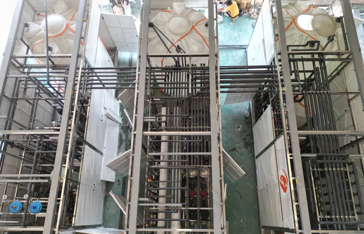
The photograph illustrates industrial treatment piping and does not identify a quoted flowmeter model. Use the linked pump and acceptance articles for surrounding system context. For the flowmeter package itself, request a marked datasheet, installation drawing, signal schedule, calibration record and commissioning checklist. These documents connect the purchased instrument to a reliable operating decision and give the site team a practical basis for accepting it, maintaining it and understanding a later discrepancy.
Questions buyers commonly ask
Can an electromagnetic meter always measure RO permeate?+
No. Confirm that the actual permeate conductivity meets the selected model requirements across the operating range. Review another measurement principle when it does not.
Should the flowmeter diameter always match the process pipe?+
Not automatically. Select the instrument from flow range, velocity, pressure-loss constraints and approved installation conditions, then coordinate any transitions with the supplier.
Does a calibration certificate prove correct PLC totals?+
No. Calibration evidence concerns the instrument under stated conditions. PLC scaling, pulse weighting, resets, retention and totalizer behaviour need separate functional checks.
What drawings should accompany a flowmeter order?+
Include the measuring-point process boundary, piping orientation, filling conditions, nearby disturbances, supports, service access and the signal connection to the control system.
Turn the guide into a project brief.
Final process selection and performance commitments should follow the complete feed-water analysis, application requirements, site utilities and approved technical agreement.