A resin trap limits the downstream consequence of media escaping an ion-exchange vessel. Its slot arrangement, hydraulic capacity and fault response must be coordinated with the actual resin and operating states; it does not repair a damaged vessel distributor.
Define the failure being contained
Identify which resin-containing vessels can release media and which downstream equipment is vulnerable. Include softeners, demineralizers, polishers and common headers where applicable. Review normal service and regeneration flow paths separately. An internal collector failure can release more material than routine trace carryover, so define the event the trap is intended to contain. State whether the objective is detection, temporary retention, protection until isolation or another explicitly agreed function.
Johnson Screens identifies resin traps as protective devices associated with ion-exchange and high-purity systems. That establishes the component class, not a guarantee that any offered strainer can contain every vessel failure. Ask the supplier to state the design boundary and residual risk. A trap should support an operable response to escaping media while the vessel fault is investigated. It should not be presented as permission to continue running a damaged distributor indefinitely.
Obtain actual resin-size information
Request the resin grade, bead-size distribution and relevant minimum retained size from the resin supplier. Include mixed grades, changes after service and any credible fines. Slot selection needs a documented basis; a generic mesh description may not define the offered opening or manufacturing tolerance. Ask the strainer vendor to explain how its retention geometry relates to the actual media and which particle fraction can still pass through it.
Distinguish intact beads from broken fragments and non-resin deposits. A slot selected to retain the intended beads may not remove every fine particle downstream. If fines control is a separate requirement, evaluate a suitable barrier and its hydraulic consequences explicitly. Keep resin retention separate from a water-quality polishing claim. The component does not remove dissolved ions merely because it sits after an ion-exchange process, and it should not receive credit for an unrelated analytical result.
Send the feed-water analysis, target quality, required capacity and operating profile. We will help structure the next engineering questions.
Send your project inputsMap every flow path and operating state
Mark the proposed location on the piping diagram and follow service, standby, regeneration, rinse and transfer paths. Confirm which routes actually need downstream protection. Show flow direction, possible reverse flow and any bypass. A trap located on one outlet may leave another common connection unprotected. Review the consequence of an incorrectly positioned valve during changeover and identify how the control sequence verifies the intended route.
For duplex or parallel vessels, decide whether traps are individual or common and explain the maintenance consequence. Individual devices may help identify the source of carryover, while a common arrangement has different isolation and capacity requirements. Do not assume they are equivalent. Include minimum and peak flow, temperature, pressure and any regeneration chemistry that can reach the device. The offered strainer must be evaluated for the full actual exposure, not only normal treated-water service.
Calculate clean and loaded hydraulic behaviour
Ask for clean pressure loss at the relevant flow range and a justified basis for the allowable loaded condition. State where differential pressure is measured and what measurement range is appropriate. A large nominal pipe connection does not establish useful screen area or resistance after resin accumulates. Request a sectional drawing with the active retention area and flow distribution so the hydraulic basis can be checked against the actual offered construction.
Consider the event when a substantial media quantity reaches the trap. Define whether the device can retain that load while flow is stopped and which upstream protection prevents damaging pressure. The response must be coordinated with pump and vessel limits. A protective screen that plugs can create a new hydraulic problem if its isolation logic is missing. Review that condition explicitly rather than accepting a clean-water pressure-drop curve as complete evidence of protective performance.
Specify materials and mechanical interfaces
Review screen material, housing, seals, fasteners and connection types against water chemistry, regenerants and cleaning agents. Include temperature transitions and any mixed chemical exposure from incorrect sequencing that the project design considers credible. Request the offered manufacturer's pressure and differential-pressure limits. Do not infer a component's allowable service solely from the nominal rating of its flanges or from the material name printed on a quotation.
Confirm supports, orientation, drainage and space to withdraw the screen element. If observation is provided through a transparent section, obtain its actual operating limits and inspection requirements. A clear view can aid detection but does not replace a suitable isolation procedure. Provide a safe method to confirm depressurization before opening the device. Include how retained resin is collected and identified so investigation does not introduce avoidable contamination into a high-purity process.
Make detection and response explicit
Decide how media presence is detected: inspection, differential-pressure trend or another offered method. Explain each limitation. A small amount of resin may not create a large pressure change, while pressure rise can result from other deposits. Establish which observation prompts investigation and which condition stops the affected train. Keep these states distinct in the operating instructions so a gradually fouling screen is not confused with a confirmed internal vessel failure.
Define the response when a trap is unavailable, isolated or bypassed. If the plant permits temporary operation, document the authorization and downstream consequence in the site's operating philosophy. The normal display should identify reduced protection. Avoid a hidden bypass position that allows the line to appear healthy while the retention device is out of service. Where continuous water supply matters, coordinate standby capacity with the time needed to inspect and repair the resin vessel.
Test installation and protective logic
Before shipment, inspect the offered slot geometry, workmanship and materials against approved documentation. Agree how dimensions or retention evidence are verified without damaging the element. At site, confirm flow direction, measurement connections, isolation, drain and maintenance access. Use approved safe simulations to demonstrate alarms and interlocks. Do not intentionally release process resin into critical downstream equipment merely to show that the operator display responds.
Document how the trap is cleaned, inspected and returned to service after actual carryover. Include the investigation of the upstream distributor and confirmation that the source fault is resolved. Record the retained material and vessel identity where multiple trains share a header. A complete acceptance package should give operators a practical sequence for containment and recovery, rather than ending at a successful clean-water flow test with no guidance for the event the component was purchased to address.
Send a resin-trap RFQ with a defined boundary
Send Baihuipu vessel diagrams, resin grades and size data, operating flow states, chemistry, pressure limits and downstream sensitivity. Request an offer that explains retention basis, screen area, loaded hydraulic limits, detection and maintenance. Include interfaces with pump protection and vessel isolation. Agree what the device is expected to contain and which consequences remain outside that boundary, so the purchase order describes a reviewable protective function rather than an undefined guarantee against all media escape.
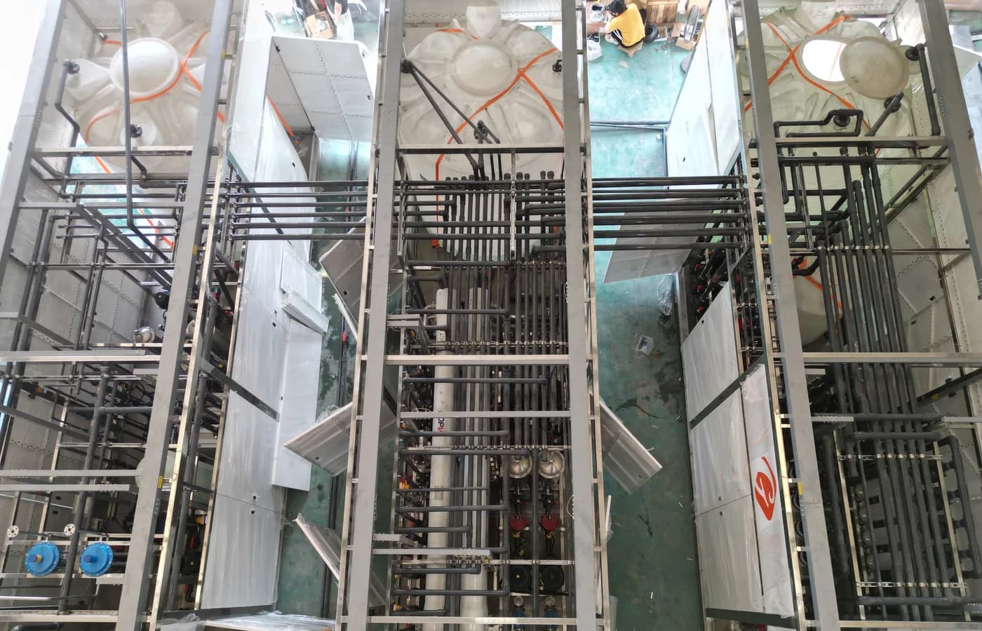
The photograph depicts treatment piping and equipment under assembly as context. It does not identify a resin trap or demonstrate slot retention. Use the offered drawings and inspection evidence to assess the actual component. The linked softener and polishing articles explain different process choices; this enquiry addresses the physical media boundary after those choices have been made. A well-defined trap protects that interface while keeping the underlying vessel's condition and repair responsibilities visible.
Questions buyers commonly ask
Does a resin trap repair a failed distributor?+
No. It can contain or help detect media escape within its design boundary. Investigate and correct the upstream source of carryover.
Can one standard slot size suit every resin?+
Use the actual media-size data and offered slot tolerance. Define which beads or fragments must be retained and which fines may pass.
Is differential pressure a complete resin detector?+
No. Small carryover may not raise it significantly, and other deposits can raise it. Specify complementary inspection and response procedures.
Why assess the loaded condition?+
A trap retaining media can restrict flow. Coordinate allowable differential pressure and isolation with the pumps and vessels it protects.
Turn the guide into a project brief.
Final process selection and performance commitments should follow the complete feed-water analysis, application requirements, site utilities and approved technical agreement.