
A semiconductor ultrapure water system is a connected generation and distribution utility, not simply an RO skid. The design begins with approved point-of-use quality requirements, then aligns pretreatment, RO, EDI or other deionization, final polishing, storage, loop materials, monitoring and validation with the actual process risk.
Start with the semiconductor use point, not a generic purity label
A semiconductor ultrapure water system should be designed from the process use point backwards. Cleaning, rinsing, wafer handling and support operations can have different contamination sensitivities, flow profiles and sampling expectations. A requirement such as ‘high purity’ is not enough to select equipment. The project team needs a controlled specification that identifies the relevant water-quality parameters, measurement methods, sample locations, normal and peak demand, pressure at the use point and the consequence of an excursion.
That discipline also prevents a common procurement error: quoting a generation skid without defining the distribution system. Water can change after it leaves the treatment room. Storage design, tank venting, recirculation, pipe material, dead-leg control, final filtration, sanitization strategy and point-of-use interfaces can all influence whether the specified condition is available where production actually consumes it. The design boundary must therefore be clear before capacity or polishing equipment is frozen.
For facilities at an early planning stage, record what is known and what remains provisional. Process owners can define the intended use and operating profile; engineering can map utilities, drains, space and expansion constraints; the water-treatment supplier can identify the analysis and design data still required. This avoids presenting a preliminary configuration as a performance guarantee.
- Define quality at each approved point of use.
- Separate continuous demand from short production peaks.
- Identify system boundary: generation, storage, loop and final polishing.
- Document unknowns before selecting a final process route.
Build the design basis around actual source-water risk
The source-water analysis establishes the first engineering boundary. Municipal, well, surface and recycled waters do not present the same risks. TDS, hardness, alkalinity, silica, iron, manganese, chlorine or other oxidants, turbidity, organics, microbiological condition and seasonal variation can each alter pretreatment, recovery and membrane-protection choices. A single old laboratory result is useful for an initial discussion, but the final design should state how representative it is and what variation has been observed.
Pretreatment is selected to protect the downstream process, not to make a flow diagram look complete. Depending on the feed, a route can include filtration, activated carbon, softening, dosing, ultrafiltration, dechlorination or other measures. The proposal should identify pretreatment outlet conditions, monitoring points, backwash or regeneration requirements where relevant, and the response if a critical upstream limit is exceeded.
For a semiconductor project, the incoming water report and the point-of-use quality report should be reviewed together. This allows the team to distinguish a process need from a treatment assumption. It also helps establish which measurements belong to the owner, which to the EPC contractor and which are verified during factory and site testing.
- Use representative, dated feed-water results.
- Review silica, oxidants and hardness with the membrane and polishing strategy.
- Confirm seasonal or source-switching variation.
- Specify sampling points before equipment layout is released.
| Design input | Why it matters | Confirm with |
|---|---|---|
| Point-of-use quality | Sets polishing and distribution controls | Process owner / quality team |
| Feed-water variation | Sets pretreatment and RO risk | Water analysis and site history |
| Demand profile | Sizes generation, storage and delivery | Production and facilities teams |
Send the feed-water analysis, target quality, required capacity and operating profile. We will help structure the next engineering questions.
Send your project inputsUse RO as the main desalting barrier and define the polishing route
Reverse osmosis commonly provides the principal dissolved-solids reduction stage in a high-purity system. Its performance depends on feed chemistry, temperature, membrane selection, flux, recovery, pretreatment and control of scaling and fouling risk. It should not be specified as a fixed ‘standard’ capacity without those conditions. Buyers should ask for the design basis behind the stated permeate flow and how the reject stream, flushing and cleaning strategy are handled.
A second RO pass can provide additional ionic reduction and operating margin where the requirement justifies it. EDI is frequently evaluated after suitably conditioned RO permeate when continuous deionization is needed without the routine acid and caustic regeneration used by a conventional mixed-bed polishing stage. The correct route depends on the required quality, feed stability, monitoring strategy, site chemical-handling policy and the performance responsibility written into the technical agreement.
Final polishing and distribution controls must be selected around the approved use-point target. Terms such as 18.2 MΩ·cm should only be used where the project specification, measurement method, temperature compensation and sample location explicitly require them. A technical article or early proposal should not imply that every semiconductor application has the same water-quality target.
- RO design requires stated recovery, temperature and membrane assumptions.
- Double-pass RO and EDI solve different engineering questions.
- Polishing is selected from the written use-point specification.
- Avoid generic purity claims without an agreed measurement basis.
Plan storage, distribution and contamination control as one system
The generation plant may produce stable water while the distribution network introduces quality risk. Storage volume should balance demand buffering, operating continuity and acceptable residence time. Tank construction, vent filtration, overflow arrangement, cleaning access and recirculation should be chosen together rather than left to a late civil or piping package.
Distribution design considers pipe material, weld or joint quality, branch geometry, recirculation velocity, pressure control, sanitization method, sample points and the interface to production tools. The desired loop arrangement depends on the facility layout and risk assessment. A large central system and several local polishing points can be appropriate in one project, while another project may require a different architecture. The reason should be traceable to the process requirement rather than a preferred supplier template.
Instrumentation is part of the contamination-control strategy. Conductivity or resistivity, flow, pressure, tank level and differential pressure can support normal operation, but they do not replace an agreed water-quality verification plan. Define which instruments are operational indicators, which are quality release points, how alarms are handled and who reviews trend data during commissioning.
- Define tank residence-time and recirculation strategy.
- Avoid uncontrolled branches and inaccessible sampling locations.
- List critical instruments, alarm actions and calibration responsibilities.
- Align loop scope with the process owner and facility layout.
Size capacity from the production profile and resilience plan
Capacity selection starts with the point-of-use demand curve, not just an average daily volume. Identify normal consumption, peak events, shifts, maintenance windows, future production phases and how long the process can operate from storage during an equipment interruption. That information determines the balance among generation rate, tank volume, distribution duty, standby equipment and expansion allowance.
Redundancy should be evaluated by function. A standby pump may protect delivery pressure but not protect a treatment stage; a parallel RO train may support production but require compatible pretreatment, controls and drain capacity. The RFQ should describe the desired availability philosophy and the maintenance capability of the site rather than assume that ‘N+1’ means the same thing for every package.
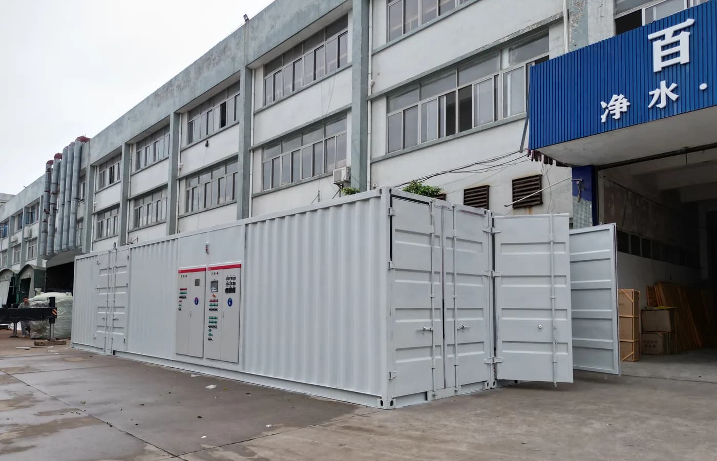
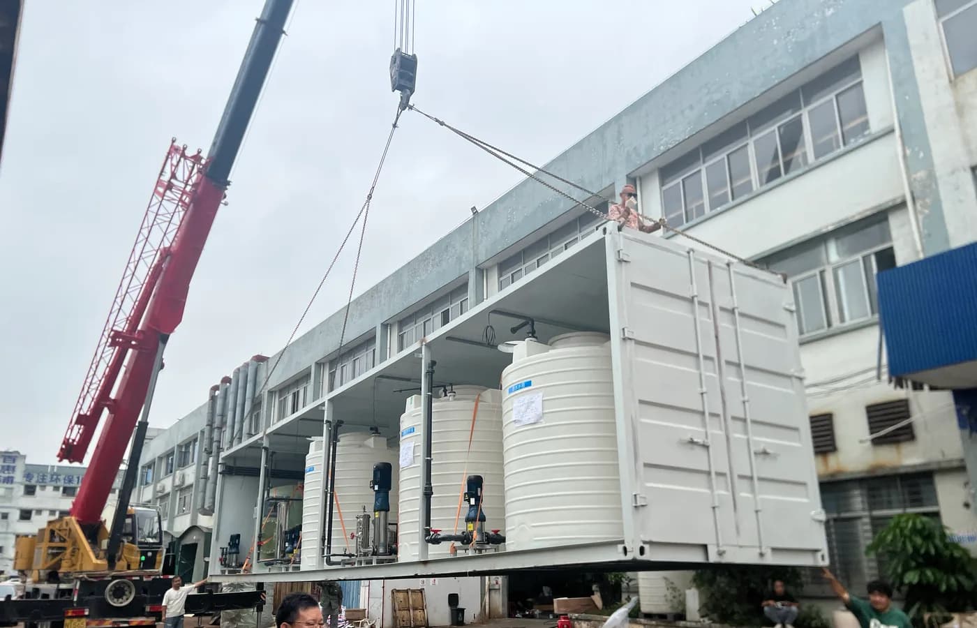
The 150 m³/h Semiconductor Ultrapure Water System project provides a published case-study reference for capacity context. Its page should be used as a project record, not as a universal design template: final feed-water quality, use-point target, distribution scope and acceptance criteria remain project-specific.
- Provide normal and peak use-point demand.
- State operating hours, expansion plans and interruption tolerance.
- Define redundancy by process function.
- Use published case studies as references, not generic guarantees.
Turn the concept into an accountable procurement package
A procurement-ready package normally includes the water analysis, product-water specification, capacity profile, site utility details, space or layout restrictions, codes or preferred components, documentation expectations and schedule. It should also clarify whether the supplier is responsible for generation only or for storage, distribution, final filtration and point-of-use integration. Ambiguity at these boundaries is a frequent source of commissioning delay.
Factory acceptance testing should follow an agreed checklist. Typical scope may include tags, piping completion, panel function, instrument signals, alarms, interlocks, pump direction and an operating run with available test water. A factory test cannot reproduce all site conditions, so the report should state water source and limitations. Site commissioning then records feed conditions, stable operating data, sampling results and open items against the approved acceptance basis.
For a practical next step, compare the Ultrapure Water System and EDI System product pages with the Semiconductor solution page, then send the water analysis and use-point duty through the enquiry route. This creates a traceable path from technical guide to product selection, industry context, project reference and engineering review.
- Confirm technical boundary and responsibility matrix.
- Agree FAT and commissioning evidence before fabrication.
- Keep product-water limits, sample points and test methods together.
- Submit the source-water analysis with the RFQ.
Align validation evidence with the semiconductor project boundary
A high-purity water project needs evidence that follows the agreed boundary. Before fabrication, establish which drawings, material records, instrument data, cleaning or flushing records, factory checks and site test results will be supplied. The list should distinguish between equipment-level evidence and evidence that depends on final installation, source water, distribution completion or process-tool connection. This makes the final acceptance process more transparent for the owner, EPC and supplier.
Commissioning should use an agreed sampling and review plan. Record the water source at the time of testing, operating flows and pressures, tank and loop condition, instrument calibration status, sample locations and any limitations caused by unfinished downstream work. If an outlying result occurs, troubleshooting should first check the defined system boundary, sample method, upstream condition and process alignment rather than treat a single reading as proof of a generation-skid fault.
For long-term operation, retain baseline trends, preventive-maintenance tasks, preservation procedures and change-control records. A distribution modification, source-water change or production expansion can affect the original water-quality risk assessment. Keeping the design basis and operating history together gives the plant a stronger basis for future upgrades than relying on a generic UPW configuration.
- Agree deliverables and acceptance scope before fabrication.
- Separate factory evidence from site-dependent validation.
- Record sample method, location and operating conditions.
- Maintain baseline and change-control records after handover.
Review constructability and long-term change control
A technically correct process route still needs a buildable layout. Review floor loading, access paths, lifting, drain points, chemical containment where applicable, ventilation, panel clearances, instrument service access and connection points before final fabrication. If storage and distribution are supplied separately, their schedule and interface drawings must be controlled so the generation package is not installed against an incompatible downstream design.
Change control is especially important when a semiconductor facility expands or changes source water. Any new process tool, branch, tank, pretreatment adjustment or source-water switch can alter demand, residence time, contamination risk or upstream operating conditions. The original water-treatment supplier’s design record is useful only when updated project data is reviewed against it.
The same discipline applies to documents. Keep the approved P&ID, layout, control narrative, instrument list, operating instructions, FAT records, commissioning data and water-quality trend history in a controlled handover package. This helps future engineering teams assess an expansion from evidence rather than assumptions.
- Verify maintenance and construction access on the approved layout.
- Control interfaces between generation and downstream distribution.
- Review source and process changes against the original design basis.
- Retain drawings and operating records as a controlled project package.
Questions buyers commonly ask
What is the first input needed for a semiconductor ultrapure water system?+
Start with approved point-of-use quality requirements, demand profile and a representative source-water analysis. Equipment selection follows those inputs.
Does every semiconductor application require 18.2 MΩ·cm water?+
No. That value should only be specified when it is part of the approved project requirement with a defined measurement basis and sample location.
Can RO alone supply semiconductor process water?+
RO is often the main desalting barrier, but the required polishing, storage and distribution controls depend on the confirmed use-point specification.
What should be included in an RFQ?+
Provide water analysis, target quality, peak and daily demand, operating profile, utilities, layout constraints, delivery location and required documentation.
Turn the guide into a project brief.
Final process selection and performance commitments should follow the complete feed-water analysis, application requirements, site utilities and approved technical agreement.