At low dissolved-oxygen concentrations, the sample path can influence the result as much as the sensor choice. Industrial buyers should specify a closed representative interface, appropriate method capability and a verifiable response before using trace DO data for process decisions.
Define the measurement boundary and purpose
Identify where dissolved oxygen matters and what decision the result will support. A trace measurement after a gas-removal stage answers a different question from a sample collected at the end of a distribution loop. State the location on the process drawing and the required reporting units. Obtain the process owner's decision limit and acceptable uncertainty instead of borrowing a familiar number from a different application or describing the requirement only as low oxygen.
Clarify whether the instrument is for trend analysis, investigation, quality release or equipment protection. Specify the response to an elevated result and the available time before affected water reaches its destination. A useful analyzer must serve that response within the installed plant. Include operating temperature, flow variation and shutdown states because a sample arrangement that represents normal circulation may no longer represent the process when a branch is isolated or a pump has stopped.
Select a method suited to trace conditions
Review optical and electrochemical alternatives against the actual range and installation. Manufacturer portfolios cover different dissolved-oxygen duties; an instrument suitable for a biological aeration basin is not automatically suitable for trace analysis in pure water. Request documented capability around the decision point, including response, stability and relevant dependencies. Ask the supplier to distinguish catalogue resolution from defensible measurement performance under the conditions expected at the plant.
Provide water chemistry, temperature, pressure and any treatment residuals that might affect sensor or sample-system compatibility. Identify maintenance and consumable requirements for the proposed technology. Ask how the manufacturer recommends verifying its performance near the intended range. Avoid selecting a method on the assumption that one sensing principle is universally superior. The choice should follow the required uncertainty, response, operating support and actual sample interface rather than the appeal of a product label.
Send the feed-water analysis, target quality, required capacity and operating profile. We will help structure the next engineering questions.
Send your project inputsPreserve the sample through a closed path
Show the entire route from process connection to sensor and final discharge or return. Evaluate every potential source of air ingress, including fittings, seals, tubing and sample conditioning. Use manufacturer-supported materials and connection methods for the trace duty. A sensor can report the oxygen present in its flow cell accurately while that water no longer represents the process. The specification should make sample integrity a supplier deliverable rather than an unreviewed site responsibility.
Minimize unnecessary dead volume and provide a documented flushing approach. Review how changes in pressure and temperature affect the path and whether gas can enter or leave the liquid before measurement. Include accessible leak checks and a way to identify inadequate sample flow. If a cooling interface is required, assess its construction and integrity as part of the sample system. Do not assume an open cup or loosely connected hose can provide a valid comparison at trace concentrations.
Control pressure, flow and temperature
State sensor and flow-cell operating limits and request a conditioning arrangement that maintains them across the process envelope. Record the intended measurement temperature and any correction used in reporting. Review the drain or return pressure rather than treating it as an unrestricted outlet. Flow restriction or pressure changes can alter sample delivery and introduce behaviour that operators may mistake for a process oxygen change. Provide enough indication to diagnose those conditions.
Position valves and regulators according to the selected manufacturer's guidance and approved sample design. Include isolation and maintenance provisions without creating an avoidable air-entry route during normal service. Ask the supplier to explain how the system stabilizes after interruption and how long operators should wait before using the result. Acceptance should examine this recovery behaviour because maintenance and restart are often the conditions under which a nominally low-oxygen process produces misleading measurements.
Demonstrate response and distinguish lag
Account for sample transport, flow-cell exchange, sensor response and signal processing separately. A rapid electronics update does not establish a rapid process-to-control response. Define the intended test and explain which part of the chain it verifies. Where controlled challenge conditions are used, follow the instrument manufacturer's procedure and the site's approved practice. Do not create an uncontrolled process contamination merely to produce an easy visible change on the analyzer screen.
Trend response during a representative transition and retain the raw data, sample conditions and timestamps. Identify whether a long tail reflects sensor recovery, stagnant sample volume or a real process change. Compare the observed delay with the available protection time. If the system cannot support an automatic response, revise the control purpose or interface rather than presenting a trend instrument as a proven release barrier. Document any limitation clearly in the commissioning record.
Plan verification and maintenance records
Specify the manufacturer's calibration and verification approach with the standards, gases or other equipment required for the selected method. Keep reference conditions and traceability appropriate to the site's quality system. Define what establishes readiness after sensor service or sample-path opening. A maintenance action can temporarily change both the sensing condition and the water reaching it, so return to service needs a documented stabilization and review step rather than a simple power-on indication.
List replaceable parts and consumables, their storage needs and expected availability at the destination. Provide accessible maintenance space and a means to isolate the instrument safely. Record interventions alongside oxygen trends so later investigations can identify discontinuities. If a portable instrument is used for comparison, review its own sample integrity and method suitability first. Agreement between two poorly controlled open samples does not establish that either represents the low-oxygen process condition.
Connect valid analysis to plant decisions
Send measured value, timestamp and diagnostic quality to the receiving control system. Define faults for inadequate sample flow, sensor service, failed verification and communication loss. State how a retained value is identified when no new measurement is available. A controller should not treat a stale low result as evidence that current water meets the process requirement. Keep quality status visible to operators and in stored data used for technical review.
Test the response to elevated oxygen and to unavailable measurement as separate scenarios. Confirm alarm routing, any diversion or hold state and the authority needed to resume production. Include the consequences of analyzer bypass during planned maintenance. If the result is used only for trending, say so in the operating documents and avoid implying that automatic protection has been demonstrated. The acceptance record should match the actual decision role assigned to the instrument.
Prepare a trace-oxygen monitoring enquiry
Send Baihuipu the process diagram, decision limit, expected range, water chemistry and full sample conditions. Include the required response time, quality-status interface and maintenance support. Request the sensor, closed sampling panel and acceptance method together. The storage and distribution guide can help identify possible sampling boundaries, while the carbon-dioxide degassing guide addresses a separate gas and treatment objective that should not be confused with oxygen measurement.
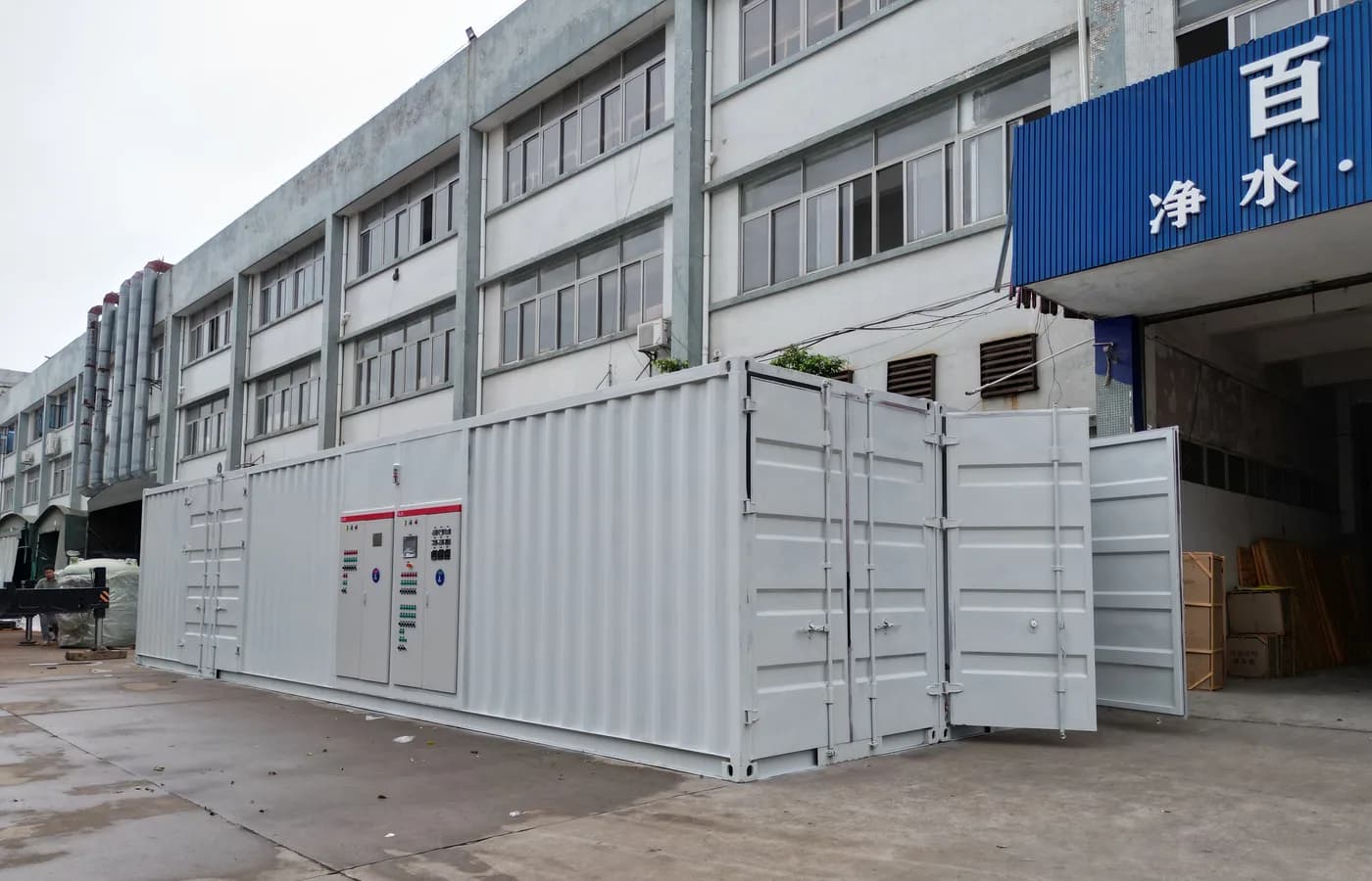
The featured photograph shows high-purity water equipment and controls as application context; it does not depict a trace DO analyzer or demonstrate oxygen concentration. Confirm the instrument and sampling details through the supplier's documentation and site evidence. A sound purchase preserves the water being measured and makes the result's age and validity visible. Those features allow a low reading to support a defined engineering decision rather than merely look reassuring on a display.
Questions buyers commonly ask
Can an open grab sample verify trace dissolved oxygen?+
Opening a sample to air can change oxygen concentration. Use a suitable controlled comparison method.
Does display resolution establish accuracy?+
No. Request documented performance and uncertainty around the actual process decision point.
Is carbon dioxide removal evidence of low oxygen?+
No. They are different gases and require appropriate process assessment and measurement.
Why record sample-system maintenance with trends?+
Opening or servicing the path can affect sample integrity and stabilization, which must be considered when interpreting subsequent results.
Turn the guide into a project brief.
Final process selection and performance commitments should follow the complete feed-water analysis, application requirements, site utilities and approved technical agreement.