A UF membrane integrity testing package needs more than a compressed-air connection and a pass lamp. Its valves, instruments, test boundaries and records must support a manufacturer-approved method. Define that package during procurement so operators can distinguish a valid membrane test from a failed setup, an external leak or an interrupted sequence.
Define what the integrity test must demonstrate
State the membrane model, rack arrangement and intended purpose of testing. Direct integrity testing applies a physical challenge to an isolated membrane assembly. Online filtrate turbidity or particle monitoring provides different information during normal production. Specify how these methods will be used together rather than treating one instrument reading as a complete substitute for the other. The purchase specification should identify which equipment boundary is being tested and who approves the method.
DuPont's IntegraTec process manual distinguishes direct and indirect methods and describes pressure-decay testing for suitable modules. Its particular settings belong to the stated membrane and system configuration. For another module or rack, obtain the supplier's approved test pressure, stabilization period, measurement interval and acceptance limit. Do not copy a setting from an unrelated installation, and do not turn a generic industrial procurement article into a claim of validated pathogen removal or regulatory treatment credit.
Draw an unambiguous test boundary around each rack
Mark the feed, concentrate, filtrate, drain and air connections on a test-specific schematic. Identify which valves isolate the rack from production equipment and neighbouring racks. Show the required position and status of each valve at every step. A test can be misleading if air escapes through an overlooked connection or water enters from another train. The process drawing should make these paths visible before a controls programmer is asked to automate the sequence.
Review shared headers carefully. Confirm whether one rack can be tested while another continues producing water and how crossflow or backfeed is prevented. Identify the permitted condition of downstream storage and pumps during the test. Where valve tightness affects the result, define how it will be checked and maintained. A rack with damaged isolation valves may produce an invalid or failed result even when the membrane fibres remain intact, so boundary faults need their own diagnosis.
Send the feed-water analysis, target quality, required capacity and operating profile. We will help structure the next engineering questions.
Send your project inputsSpecify the air supply independently of backwash aeration
Ask the membrane supplier to define air cleanliness, moisture condition, supply pressure and required regulation for the approved test. The existing air-scour blower should not automatically be assumed suitable. Include the regulator, isolation, indication and protection needed to keep the assembly within its permitted pressure. Agree the delivery responsibility for site compressed air and the point where the skid supplier's scope begins. Put those interfaces in the utility schedule rather than leaving them as commissioning assumptions.
Describe controlled admission of air and the approved route for displaced water. Request a review of pressure limits across the membrane, module, valves and connected piping. Include failure of regulation or valve actuation in the controls review. The test should run under an approved procedure with suitable personnel protection. It should never rely on an operator increasing pressure until a visible response appears, because that approach can exceed equipment limits and invalidate the intended test method.
Choose instruments that can resolve the acceptance decision
Select pressure measurement from the required test range and the smallest change relevant to the decision. Ask for accuracy, resolution, repeatability and calibration provisions at the actual test conditions. A transmitter adequate for ordinary process-pressure indication may be unsuitable for a small pressure-decay measurement. Specify the installation location, connection and signal processing so the displayed value corresponds to the defined test volume instead of an unrelated section of the air manifold.
Require the supplier to explain how stabilization, temperature variation and trapped volumes are handled in the approved procedure. Record the actual start and end pressures, elapsed time and any other inputs used to calculate the result. Where an automatic calculation is used, document its units and formula. Demonstrating that a PLC can display a pass or fail message is insufficient; the buyer should be able to reconstruct the decision from saved measurements and the configured acceptance criteria.
Build readiness checks and invalid-test states into controls
Define the required membrane condition before testing, including wetting and any preparation specified by the module supplier. The IntegraTec guidance notes that fouling can mask defects, making preparation relevant to interpretation. Confirm the rack is in the correct operating mode, valve alignment is complete and the pressure signal is healthy before starting the measurement interval. Record why a test was prevented or aborted instead of silently skipping a scheduled test and leaving the previous pass indication active.
Use separate states for not tested, testing, passed, failed and invalid or interrupted. Loss of air supply, a sensor fault or an incomplete sequence should not be treated as a fresh pass. Agree the required response to each state, including operator notification and any restriction on returning the rack to production. Keep test authorization and return-to-service permission explicit so a control-system restart does not erase an unresolved result or automatically release an unassessed membrane rack.
Plan fault localization and controlled return to production
Ask how a failed result will be investigated before ordering replacement modules. The troubleshooting plan should distinguish the test boundary, instrument health, external seals and membrane condition. Provide the inspection access and module identification required by the manufacturer's method. If transparent observation sections are specified, select their location and rating deliberately. A photographic record or module map can help a service technician connect the test result to the physical rack without guessing which connection was observed.
Repairs, module isolation and fibre-repair methods must follow the applicable supplier instructions and approved site procedure. After corrective work, document the action and repeat the required approved assessment before release. Include the prescribed venting, flushing and restoration sequence in the operating manual. Where a failed rack is removed from duty, check the production plan for the remaining equipment. Integrity testing has a real availability cost, which belongs in the operating schedule rather than being hidden in the nominal filtration capacity.
Specify records and acceptance exercises before delivery
A useful record identifies rack and module arrangement, date and time, operator or automatic trigger, software revision, configured criteria, measured values and result status. Include alarms, invalid-test reasons and corrective actions. Define how records can be exported and retained by the owner. Changes to pressure limits or decision logic should be controlled and visible. A dashboard that only stores the most recent result cannot support an investigation of an intermittent fault over several production cycles.
For acceptance, agree safe exercises that demonstrate sequencing, valve feedback, instrument fault handling, interrupted-test behaviour and record export. Any physical challenge used to establish detection capability must be designed and approved by the relevant supplier or responsible specialist. Do not deliberately damage a membrane to improvise a demonstration. Separate a functional controls exercise from evidence that the installed physical test achieves its stated sensitivity, and document any work that must be completed later under site conditions.
Request a complete UF test-subsystem quotation
Provide bidders with the membrane data, rack layout, production schedule, available utilities and required record interface. Request a test schematic, component list, instrument specifications, sequence narrative, approved criteria and maintenance plan. Identify the scope for commissioning, technician training, spare seals and periodic instrument checks. Review the quoted package with both the membrane supplier and the controls team, because an air skid alone cannot establish the validity of a test performed across an incorrectly defined rack boundary.
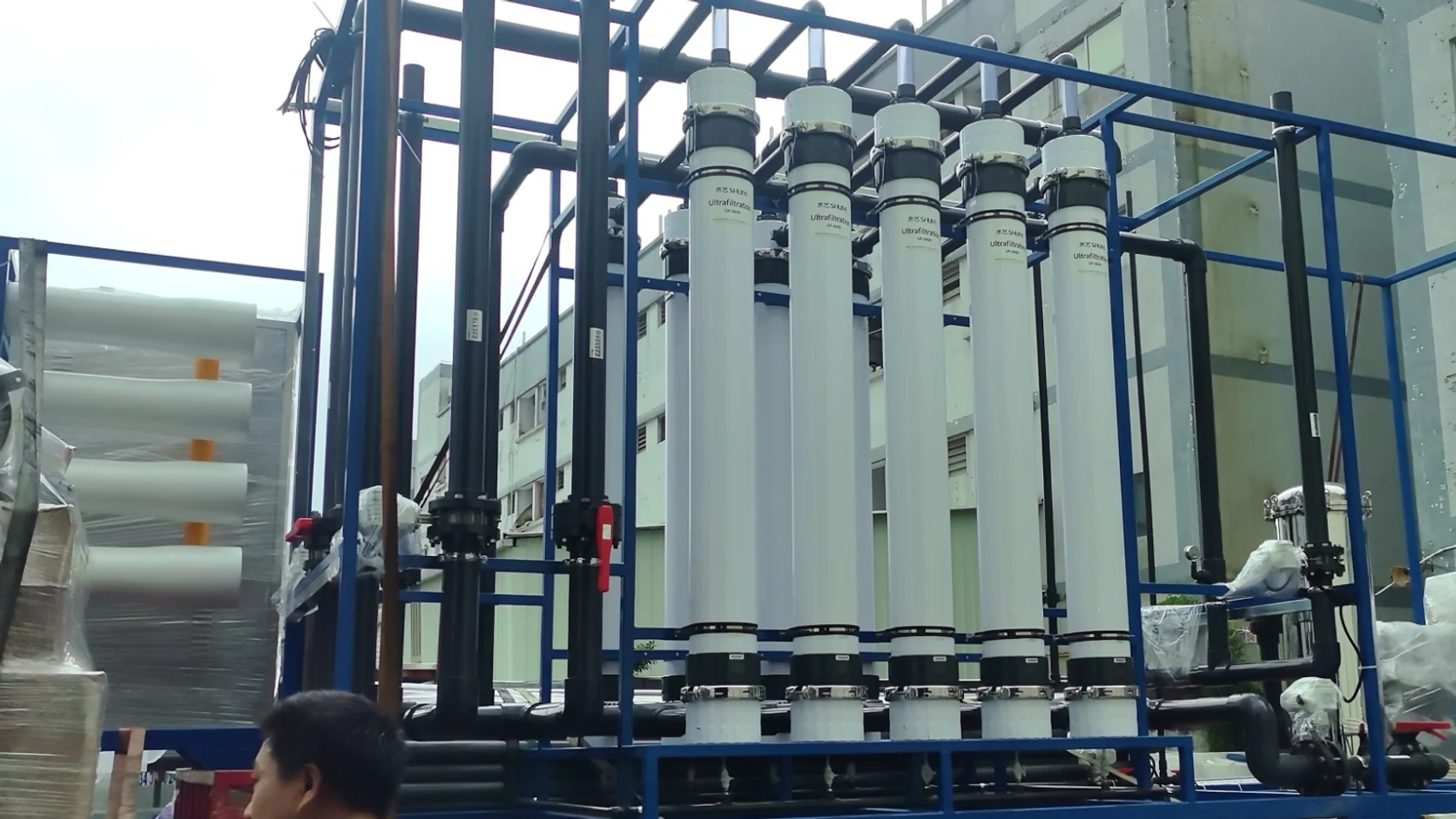
The featured UF equipment image illustrates the pretreatment context; it does not establish the presence or validation of a particular integrity-test package. Send Baihuipu your module model, rack schematic, utility details and current testing requirements for a coordinated scope review. The objective is a test subsystem that can produce interpretable evidence and guide a responsible operating decision, with clear ownership of preparation, result review, maintenance and return to service.
Questions buyers commonly ask
Does low filtrate turbidity prove UF membrane integrity?+
It provides useful operating evidence but is different from a direct physical integrity test. Specify the monitoring and testing methods required for the membrane and intended application.
Can a UF air-scour blower supply a pressure-decay test?+
Do not assume so. Confirm the approved test's pressure, cleanliness and regulation requirements with the module supplier and specify a suitable air source.
Should every failed pressure-decay test trigger module replacement?+
First investigate the approved test setup, isolation valves, external leaks and instruments. Follow the supplier's fault-localization procedure before deciding whether a membrane module needs repair or replacement.
What evidence should an automatic test retain?+
Keep rack identity, criteria, measured pressures, timing, calculation inputs, result status and interruptions. Records should distinguish a valid pass from an invalid, aborted or stale result.
Turn the guide into a project brief.
Final process selection and performance commitments should follow the complete feed-water analysis, application requirements, site utilities and approved technical agreement.