Industrial water-treatment piping can experience pressure changes during pump trips and valve movements that steady duty calculations do not capture. A useful surge assessment follows the connected pipe system, tests credible events and justifies protection on the actual installed boundary.
Extend the assessment beyond the skid frame
Define the hydraulic boundary from the upstream source through the treatment package to connected storage and distribution. Include long site lines, elevation changes and other equipment that can influence a transient. A skid may meet its steady pressure duty while an external valve or pump event creates a different condition at its connection. State which supplier owns the combined assessment rather than allowing each contractor to approve only the short pipe segment within its own delivery.
Identify components with pressure and vacuum limitations, including vessels, housings, instruments and flexible connections. Obtain their relevant manufacturer limits rather than inferring transient capability from a single nominal designation. The review should address both high and low pressures where they are credible. Do not assume that a steady design pressure check covers every event or that all components connected to the same header share identical resistance to a rapid hydraulic change.
Collect the data that drives the model
Request actual pipe routes, lengths, internal diameters, elevations, materials and support assumptions needed by the responsible analyst. Include fittings and connected volumes where they materially affect the chosen model. Identify uncertain survey information and how it will be resolved. A calculation based on an approximate sketch may help screen a concern but should not be presented as final verification of an installation whose pipe material or route is still being changed.
Provide pump curves, operating controls, relevant inertia data and manufacturer information for check valves and actuated valves. Record tank levels, boundary pressures and credible operating combinations. Ask which data are measured, supplied by a manufacturer or assumed. The report should identify sensitivity to important assumptions so the owner understands where a changed valve selection or site elevation could invalidate the result. Preserve the model input schedule with the approved equipment documentation.
Send the feed-water analysis, target quality, required capacity and operating profile. We will help structure the next engineering questions.
Send your project inputsDefine credible operating and fault events
Review normal startup and shutdown, loss of electrical power, pump changeover, valve closure and restoration of supply. Include combinations that arise from the actual controls and site arrangement. A programmed slow stop does not necessarily describe a pump losing power unexpectedly. Ask the analyst and equipment suppliers to agree which events govern the design and which are excluded with a stated reason, rather than accepting a report that examines only convenient normal operation.
Consider different tank levels, parallel train states and destination valve positions. Identify any trapped volume or line section that can become isolated during a sequence. Review potential changes in pressure boundary when another process package starts or stops. The point is to establish a useful event envelope, not to invent every imaginable failure. Tie the selected scenarios to the installed design and operating narrative so a reviewer can understand why they represent the conditions the equipment must withstand.
Review valve behaviour as physical data
Specify the actual flow-versus-travel behaviour and timing of relevant actuated valves where needed for the assessment. A controller command duration is not necessarily the hydraulic closure time. Include fail position and response after power or air loss. Ask how the selected actuator and valve combination behaves across the available utility conditions. Substituting another valve with the same connection size can change the transient and should trigger review of the assumptions affected.
Review check-valve selection against the system's expected flow changes with the manufacturer. Do not select solely from a generic claim that one style prevents hammer in every installation. Ask for the technical basis applicable to the modeled conditions. Include maintenance and failure behaviour in the operating review. Where a protective strategy depends on a valve moving as specified, define how that behaviour is commissioned and retained through inspection or testing under the site's maintenance programme.
Compare protection using the governing events
Potential measures can include revised operating sequences, appropriate valves or engineered surge equipment, depending on the analysis. Compare them against the same event set and component limits. Supplier discussions of soft pressure buildup illustrate one normal-control approach, but they do not prove protection during every power-loss event. Require an explanation of which scenarios each measure addresses and where another design feature remains necessary.
Request drawings, operating constraints and maintenance needs for any proposed protection device. Include connection size, position and interaction with the water-quality requirements of the treatment train. A device selected only to limit peak pressure may introduce another process or maintenance consideration. The final recommendation should state why the configuration is suitable on the assessed boundary, with residual limitations visible. Avoid an unsupported promise that one added accessory makes the entire plant immune to hydraulic transients.
Align control sequences and instrumentation
Translate assessed timing and permissives into the approved control narrative. Identify which settings are process-critical and how changes are authorized. Include the response to utility loss and recovery rather than only normal automatic commands. If operators can bypass a sequence, document its consequence and permitted use. A model can establish a suitable sequence while the installed controller executes something different, so the interface between calculation and automation needs explicit verification.
Select pressure measurements appropriate to the commissioning objective with the analyst. A slowly logged plant transmitter may not capture a rapid transient adequately. Define location, response and data-recording requirements for the event being checked. Include calibration and synchronization where relevant. Avoid claiming that a flat trend proves the absence of a surge when the instrument system was not capable of resolving the event. The recorded evidence must match the phenomenon the acceptance test is intended to examine.
Validate without creating uncontrolled events
Agree a commissioning plan with the responsible engineers and equipment suppliers. Use analysis, factory evidence and controlled site checks to establish the intended protections. Do not improvise abrupt closures or electrical trips merely to produce a dramatic pressure trace. The test sequence and permitted conditions should be reviewed before execution. Record what each check proves and whether any governing event remains supported by analysis rather than a direct physical demonstration.
Compare the installed configuration with the final model inputs, including valve types, timing, pipe route and tank levels. Resolve material deviations before closing acceptance. Retain settings, event traces and manufacturer documents with the report. Identify future changes that require reassessment, such as extending a header or adding another pump. This gives operations a practical basis for managing the system after commissioning rather than leaving a technically complete calculation disconnected from later plant modifications.
Prepare a surge-assessment enquiry
Send Baihuipu the connected piping information, equipment pressure limits, pump and valve data, operating sequences and site utility conditions. Request a defined assessment boundary, scenario list, input responsibility schedule and justified protection scope. Use the related pump guide to review normal duty and suction conditions, and the distribution guide for connected storage and pipe interfaces. Make the transient review an explicit deliverable where the project assessment identifies it as necessary.
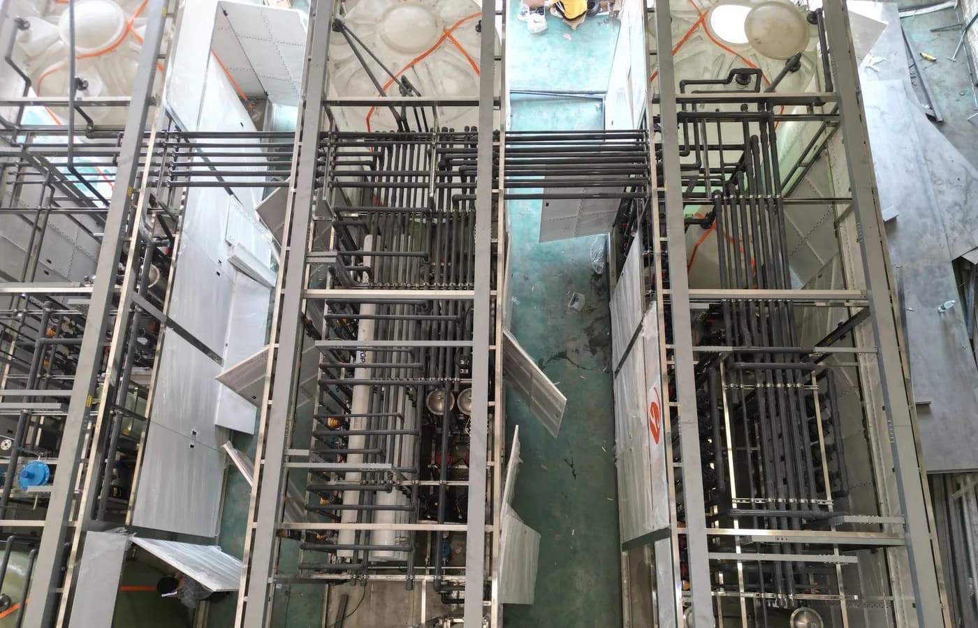
The featured photograph shows industrial piping and membrane equipment as context; it does not document surge testing or verify pressure limits. Confirm the proposed protections through analysis and an approved acceptance plan. A complete purchase makes the governing events and assumptions visible, then verifies that the installed equipment and controls match them. That evidence helps the owner manage hydraulic behaviour across contractor boundaries and future changes without relying on an unqualified water-hammer claim.
Questions buyers commonly ask
Does a soft pump startup protect against every trip?+
No. Assess power loss and other governing events separately from programmed normal operation.
Can normal pressure logging capture every transient?+
Not necessarily. Select measurement response and logging suitable for the event being verified.
Is valve command time the same as hydraulic closure time?+
No. Use the actual valve and actuator behaviour relevant to the analysis.
When should the assessment be revisited?+
Review changes that affect model assumptions, including pipe extensions, pump configuration, valve selection or control timing.
Turn the guide into a project brief.
Final process selection and performance commitments should follow the complete feed-water analysis, application requirements, site utilities and approved technical agreement.