Instrument air is a functional utility for valves and instruments across an industrial water plant. Procurement should define quality at the user, pressure during simultaneous demand, drying under real ambient conditions and the operating consequence of a compressor, dryer or common-header failure.
Separate instrument air from other air users
List the pneumatic consumers on the treatment plant and identify each function. Actuator supply, analytical equipment, membrane testing and process aeration can have different quality, flow and pressure requirements. Do not assume that one available factory air connection is suitable for all of them. Obtain the actual component requirements and define which users share a supply. This establishes the purchasing boundary before compressor capacity, drying or connection size is selected from a generic equipment schedule.
Identify whether the project includes a complete air package or only a connection to an existing header. For a shared utility, obtain evidence of supply conditions at the proposed tie-in and during relevant factory operating states. A compressor nameplate elsewhere on the site does not establish pressure or quality at the treatment skid. Clarify who owns upstream capacity, distribution losses, contamination control and the response when another plant user creates a sudden demand or supply interruption.
Specify quality at the point of use
Define required limits for particles, water and oil using the receiving equipment documentation and the site's applicable specifications. Atlas Copco's instrument-air guidance distinguishes these contamination categories and explains pressure dew point. Use that as a measurement framework, while selecting actual requirements for this project. Avoid an undefined promise of clean dry air. A meaningful specification states the quality, measurement location, operating pressure and the conditions under which the required state must be demonstrated.
Review sensitive users individually. A valve actuator and an air stream that can contact high-purity water may impose different constraints. Identify whether point-of-use filtration is required and include its pressure loss and maintenance. Keep lubricated workshop air separate where its condition is unsuitable. Quality should remain traceable through the complete supply path. Installing a dryer near the compressor does not prove that downstream piping, temporary hoses or an incorrectly connected branch cannot reintroduce contaminants before the user.
Send the feed-water analysis, target quality, required capacity and operating profile. We will help structure the next engineering questions.
Send your project inputsRelate drying to ambient and pressure conditions
Record the lowest temperature to which the distribution system and instruments may be exposed, as well as the compressor inlet environment. State pressure dew point at the defined operating pressure rather than substituting an atmospheric reading without explanation. Ask the supplier to select a drying arrangement against the actual seasonal envelope and quality objective. The correct duty is the one that prevents unsuitable moisture conditions at the users, not merely one that matches a convenient catalogue climate.
Include inlet temperature, flow variation and pressure effects in dryer selection. Review whether startup or a dryer changeover can send inadequately conditioned air downstream. Request the approved monitoring and response arrangement, including where dew point is measured when required. A display on the package may represent only one location. Clarify how its reading relates to the coldest exposed line and most demanding component so the operating team can interpret it as evidence rather than a general reassurance.
Calculate simultaneous demand and usable pressure
Obtain actuator consumption and instrument flow on a common reference basis. Map the actual sequence, including valves that move together during backwash, regeneration, shutdown or restart. Average consumption over a long cycle can conceal a short demand that lowers local pressure. Ask for a dynamic assessment appropriate to the system. Include leakage allowances on a documented basis and retain uncertainty where actual installed consumption has not yet been measured.
Establish minimum pressure at the most demanding user after line, filter and regulator losses during those events. Include long distribution runs and small flexible connections. Request a coordinated pressure schedule rather than comparing compressor discharge pressure with an actuator requirement directly. If an existing factory header is used, assess the treatment sequence alongside credible concurrent factory demand. The supply arrangement should demonstrate usable pressure where pneumatic work is performed, including at the end of the most demanding event.
Define the receiver's actual function
State whether a receiver buffers short demand, reduces compressor cycling, supports an orderly shutdown or serves another defined purpose. Obtain sizing and usable pressure assumptions for that function. A receiver volume without initial and minimum pressure does not establish available pneumatic capacity. Include the effect of shared consumers that can draw from the same stored air. If reserve air is intended for selected equipment, show the isolation and distribution arrangement that preserves that reserve.
Review drainage, inspection, installation and applicable pressure-equipment requirements with the responsible engineers. Include gauges, protective devices and access appropriate to the actual receiver. Avoid implying that any stored air can guarantee an indefinite operating period after compressor loss. The available duration depends on the defined demand, leakage, pressure and sequence. Acceptance should address the stated function using calculations and feasible demonstrations rather than relying only on the receiver nameplate volume or an untested runtime claim.
Coordinate filtration, condensate and maintenance
Request a treatment diagram showing separators, dryers, filters, drains and relevant monitoring. State which contaminants each stage addresses and which consumables require replacement. Include bypass arrangements and the quality consequence of using them. A maintenance bypass can preserve air flow while removing the conditioning on which instruments depend. Define the approved plant operating state during that work, including whether selected users must be isolated or supplied through an acceptable alternative route.
Specify condensate collection and disposal using the actual compressor and contamination conditions. Include drain failures and their indication. Provide access for replacing filters and servicing dryer components without creating an unreviewed contamination path. Ask for commissioning cleaning and inspection of new distribution piping before connection to sensitive equipment. The installed supply should deliver the required condition after maintenance as well as during initial testing, with responsibilities clear between the air-package supplier and site piping contractor.
Test utility loss and restoration
Define low pressure, poor drying, compressor unavailable and common-header isolation as distinct states where relevant. Determine the resulting position and availability of pneumatic users under the approved process philosophy. The air-system supplier should provide useful status signals, while the treatment integrator defines how affected sequences respond. Avoid assuming that a general compressor alarm establishes the state of every valve or that a still-running PLC can restore treatment when pneumatic energy is unavailable.
Demonstrate the approved response to declining air supply and its restoration using a controlled plan. Include a sequence in progress and the simultaneous restart demand. Confirm that valves and instruments return to an established valid state before automatic water release resumes. Record observed pressure at relevant users. This gives operators evidence for recovery rather than leaving them to reset alarms while a depleted receiver and multiple moving actuators recreate the original low-pressure condition.
Prepare the instrument-air enquiry
Send Baihuipu the user list, component quality requirements, pressure limits, sequence timing, site environment and existing utility data. Include receiver objectives, redundancy expectations, monitoring and condensate interfaces. Request a coordinated supply, treatment and distribution proposal with clear owner boundaries. Agree quality and dynamic-demand acceptance conditions, and document which cases rely on reviewed calculations. Keep process air and instrument air separate in capacity schedules so one duty is not unintentionally accepted using evidence for another.
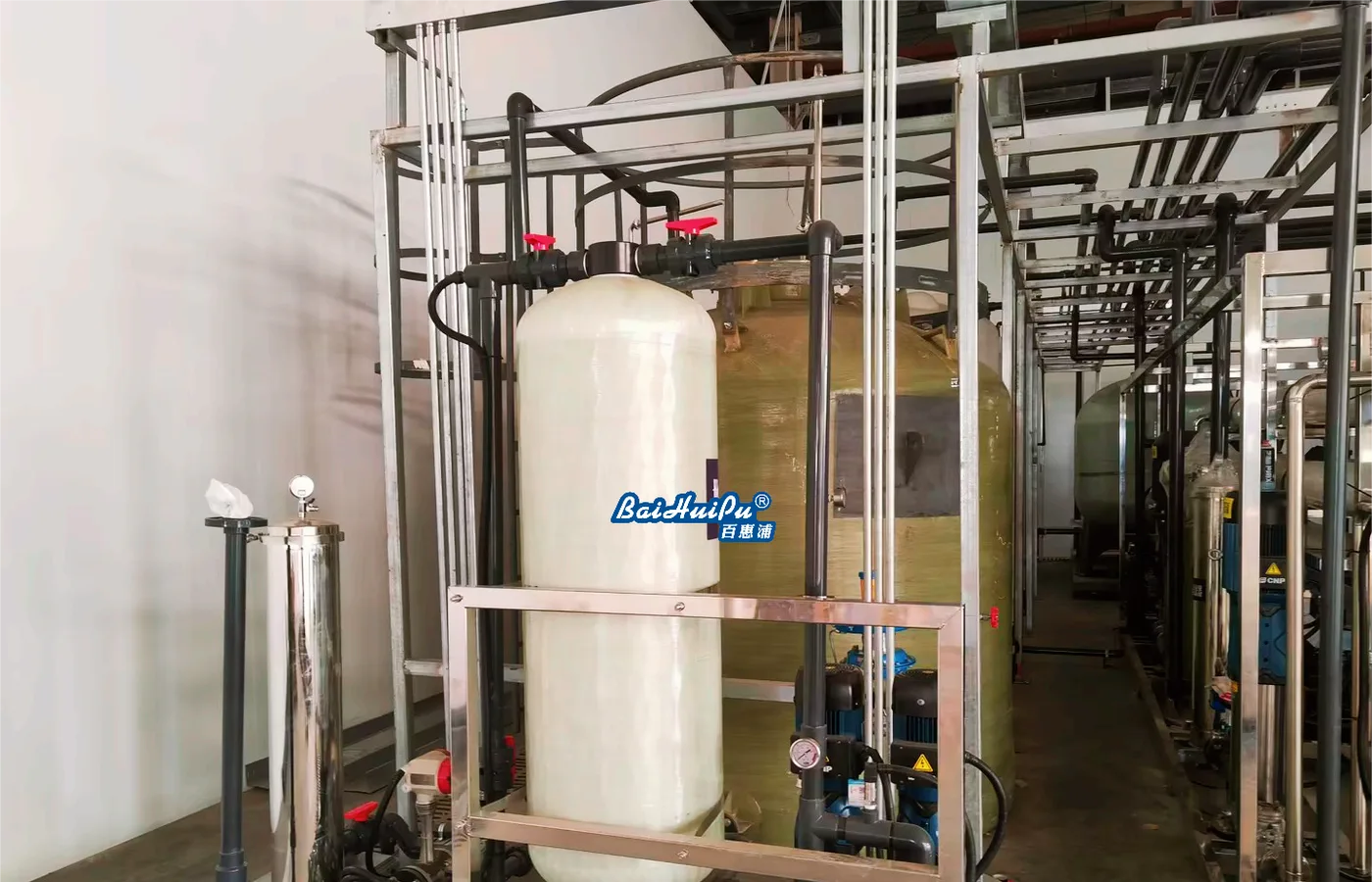
The featured image shows industrial water-treatment equipment and piping as context, not an instrument-air compressor or proof of air quality. Use offered component documents and measurements at the defined supply and user locations for acceptance. The linked UF and PLC guides address adjacent functions. A complete utility specification joins air quality, available pressure and recoverable process states without inferring pneumatic reliability from nominal compressor capacity or from a dry reading recorded under unusually favourable ambient conditions.
Questions buyers commonly ask
Is average actuator consumption enough to size the supply?+
No. Check simultaneous movements and short demand events, with pressure losses and usable receiver capacity on a common reference basis.
Why state pressure dew point at operating pressure?+
It describes moisture behaviour at that pressure. Relate it to the actual distribution temperature and receiving-component requirements.
Can a receiver provide unlimited backup air?+
No. Define usable pressure, demand, leakage and the intended sequence before assessing the reserve duration.
Does a dryer prove every user receives suitable air?+
No. Verify distribution, filters, connections and point-of-use conditions, including maintenance and bypass states.
Turn the guide into a project brief.
Final process selection and performance commitments should follow the complete feed-water analysis, application requirements, site utilities and approved technical agreement.