An actuated valve package needs a defined hydraulic duty and a demonstrated response when air, power or command is lost. Procurement should coordinate valve body, actuator, solenoid and position feedback so the plant knows the achieved flow-path state rather than only the requested command.
Define the actual valve function
Identify whether the valve isolates, diverts, throttles, drains or performs another stated duty. Provide the process fluid and normal and abnormal operating cases. An isolation valve is not automatically a suitable modulating control valve, and an open command does not establish an acceptable pressure drop. The enquiry should describe what the assembled valve must accomplish within the water-treatment sequence before body size, actuator arrangement or accessory selection is finalized.
Record inlet and outlet pressures, temperature, flow range and relevant water chemistry. Include cleaning, backwash, regeneration and stopped-pump conditions where they alter the duty. Specify permitted flow direction and reverse-pressure cases. A pipe diameter alone is insufficient for selecting the valve or actuator. The purchaser needs the pressure and flow conditions under which the body must move, remain positioned and provide the required shutoff or control behaviour throughout the actual operating cycle.
Size the actuator for the governing conditions
Ask the valve manufacturer to state torque or thrust requirements for the selected body, seat and differential pressure. Request the actuator sizing basis using minimum available air supply and the relevant operating temperature. Include breakaway and end-of-travel requirements where applicable to the offered design. A bench movement with no process differential demonstrates assembly motion; it does not establish that the installed valve can achieve the required position under the governing hydraulic load.
Include the spring-return direction or double-acting arrangement and the manufacturer's documented margins and limits. Check accessory pressure losses and the actual air condition at the actuator connection. Avoid comparing a compressor's maximum pressure with the actuator rating while ignoring local regulators or simultaneous demand. The assembled package needs a coordinated and reviewable basis so the body supplier, actuator supplier and integrator do not each assume that another party has confirmed its ability to operate at site.
Send the feed-water analysis, target quality, required capacity and operating profile. We will help structure the next engineering questions.
Send your project inputsDefine each failure state separately
Emerson's handbook describes fail-open and fail-closed behaviour in relation to loss of actuating energy. For the offered assembly, examine loss of air, loss of solenoid power, loss of command and loss of communications separately. These events do not necessarily produce the same outcome. Obtain the complete pneumatic and electrical arrangement. A label such as normally closed can be ambiguous unless the operating state and type of failure to which it refers are explicitly identified.
Ask the responsible process team to select required flow-path states for actual risks and operating consequences. Closing every valve is not a universal solution; some systems need a defined flushing, venting or relief route. Include trapped liquid and the interaction with pumps. Keep any protective-function requirements under the responsible design process. Procurement should state the required behaviour and evidence without assuming that a single spring-return accessory automatically establishes the complete plant's acceptable failure state.
Coordinate solenoids and pneumatic accessories
Specify solenoid supply, enclosure, environmental requirements and pneumatic port arrangement for the actual assembly. Review speed controls, regulators, exhaust treatment and any local manual override. Include the consequence of a blocked exhaust or lost local air connection where relevant. Accessories change actuator behaviour, so the purchased scope should identify the assembled configuration rather than a collection of compatible-looking components whose combined failure and travel characteristics have not been checked.
Define how local override is indicated and restored before automatic operation. A valve held manually in a different state can undermine a treatment sequence even when the PLC issues the correct command. Request appropriate identification and commissioning checks for tubing and wiring. Include maintenance isolation with the site's approved procedures. The objective is a valve package whose actual state and control authority remain understandable after installation, service and replacement of individual accessories.
Distinguish command, position and flow-path evidence
Provide achieved-open and achieved-closed feedback appropriate to the process decision. Identify whether feedback comes from a limit switch, positioner or another mechanism, and what it physically measures. A command echo is not position proof. Likewise, actuator travel feedback may not establish internal valve integrity if the mechanical connection or body has failed. Ask the supplier to state the limits of the feedback so the integrator can assign it an appropriate role in sequence permissives.
Specify travel timeout, conflicting feedback and intermediate-position handling. Include the response when a valve fails to reach the commanded state. Where flow must be confirmed, identify the additional hydraulic evidence required rather than treating one switch as proof of every downstream condition. Record the control narrative with the actual instrument tags. These distinctions help prevent a backwash, chemical or product-water sequence from proceeding on a requested flow path that the installed equipment has not actually established.
Review shutoff, materials and serviceability
Define the required shutoff evidence and its test conditions for the offered valve type. Include direction, pressure and any applicable leakage specification adopted by the project. Do not infer zero leakage from a closed-position indication. Review body, seat, seals and wetted accessories against the actual water and cleaning chemicals. A nominal material name should be supported by the component selection and service conditions, especially where exposure changes during chemical cleaning or regeneration.
Obtain access requirements for actuator, seat and body maintenance. Review whether the valve can be removed without disturbing adjacent critical instruments or creating an impractical pipe-support condition. Include spare seals, solenoids and replacement configuration information appropriate to the operating plan. A maintainable package should allow the original failure behaviour and feedback settings to be restored after service, rather than rely on unrecorded adjustments made during the first commissioning visit.
Coordinate travel time with the process
State any required opening and closing time and the conditions under which it applies. Review the hydraulic transient implications with the system designer, as covered by the linked water-hammer guide. Fast movement is not automatically desirable. Excessively slow travel can also disrupt a timed process or allow an unsuitable mixed flow. Ask for a coordinated range that satisfies both the hydraulic system and the treatment sequence under minimum available actuation supply.
Check travel under the relevant load and fail action rather than adjusting speed only during an unloaded bench test. Include simultaneous valve movements and the effect on shared air. Record approved settings and how they are protected from casual changes. If the process relies on a particular movement order, verify that order using achieved feedback and timing. A deterministic sequence needs evidence of what the valves do, not simply a set of start commands separated by arbitrary timer delays.
Prepare the actuated-valve enquiry
Send Baihuipu the valve list, hydraulic cases, chemistry, required failure states, air and electrical supply, feedback and maintenance constraints. Request assembled drawings and a coordinated sizing basis. Agree factory and site checks for movement, feedback, shutoff and approved failure simulations. Identify which hydraulic cases cannot be reproduced at the factory and retain the supporting calculations. This creates a reviewable acceptance boundary for the actual valve assembly and its role in the plant.
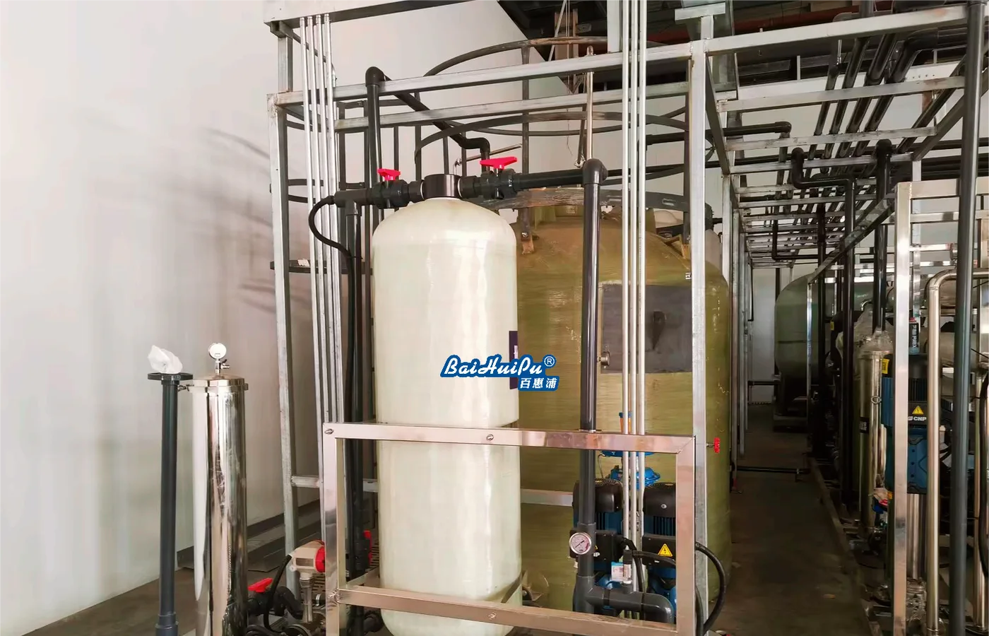
The featured photograph shows industrial water-treatment piping and equipment as context, not proof of a particular actuator or valve's failure behaviour. Use the offered assembly documents and witnessed results for acceptance. The related PLC and transient guides address adjoining design responsibilities. Coordinating those boundaries allows a buyer to compare more than nominal size and material while avoiding an unsupported assumption that an energised solenoid, an open command or a single limit switch establishes the complete water-flow state.
Questions buyers commonly ask
Does a run command prove the valve is open?+
No. Use appropriate achieved-position feedback and any additional hydraulic evidence required by the process decision.
Are loss of air and loss of electrical command equivalent?+
Not necessarily. Review the complete actuator, solenoid and accessory configuration and test each required failure state.
Does a closed limit switch prove zero leakage?+
No. Shutoff needs its own specified test conditions and evidence for the offered valve and service.
Should every treatment valve close as quickly as possible?+
No. Coordinate travel time with hydraulic transients, sequence timing and the minimum available actuation supply.
Turn the guide into a project brief.
Final process selection and performance commitments should follow the complete feed-water analysis, application requirements, site utilities and approved technical agreement.