A radar level instrument should be selected and mounted for the actual tank geometry and surface conditions. Procurement needs to establish what the instrument measures, how interference is assessed and how an invalid or stale signal affects filling, pumping and the plant operating state.
Define the level measurement decision
Identify whether the signal is used for inventory indication, pump protection, filling control or another stated function. Provide the tank dimensions, operating levels and process fluid. Distinguish liquid level from calculated stored volume. A distance measurement becomes a useful control input only after reference points, geometry and validity are correctly configured. The instrument enquiry should explain the decision the reading supports so the supplier can assess the installation and required operating evidence.
Separate ordinary continuous measurement from any independently required protective function. The responsible project team should define the protection architecture and applicable requirements for the actual tank. Do not assume that one transmitter and one PLC display establish every required overfill or dry-running safeguard. Procurement should identify which signals are used, what failure assumptions apply and who owns the combined design, avoiding an undefined expectation that a convenient level reading can carry unlimited operational responsibility.
Describe the tank and its internal obstacles
Supply drawings showing roof form, nozzles, ladders, pipes, agitators and other internals. Include the dimensions and location of the proposed mounting connection. Ask the instrument supplier to assess the beam path and potential reflections for the offered antenna and model. A narrow beam can help some installations, but a general product claim does not replace a review of this tank's geometry and its actual minimum and maximum liquid levels.
Include inlet jets, recirculation returns and the direction of surface movement. Identify equipment added after the original tank drawing was issued. A pipe or bracket introduced during installation can change the measurement environment even when the transmitter model remains appropriate. Require an as-installed review before commissioning configuration is finalized. This is especially useful when multiple contractors own the tank roof, process piping and instrument mounting and no single party otherwise checks the complete echo path.
Send the feed-water analysis, target quality, required capacity and operating profile. We will help structure the next engineering questions.
Send your project inputsReview mounting and reference distances
Obtain the manufacturer's limits for nozzle length, diameter, antenna position and measurement range. Confirm the physical reference plane used by the instrument and the reference used by the tank drawing. State the distance corresponding to zero and full process level. A consistent engineering datum prevents an apparently small installation offset from changing pump or fill decisions. Include verification of dimensions after mounting rather than relying only on the original design values entered at the factory.
Review mechanical and environmental requirements, including pressure, temperature, ingress protection and chemical exposure at the antenna and seals. Include condensation or washdown where relevant to the actual installation. Ask for access to wiring and service points without entering or dismantling the tank unnecessarily. Where measurement through a plastic wall or roof is proposed, obtain model-specific suitability and installation evidence. That is a distinct geometry question and should not be inferred merely from the absence of a metal cover.
Evaluate foam and changing surface conditions
Describe the expected surface, including foam, turbulence, floating material and deposits. Provide observations across filling, recirculation, cleaning and production changes. Ask the offered manufacturer how the model responds to those conditions and what trial or installation evidence is appropriate. Radar performance is application dependent; avoid assuming that every foam is transparent to the measurement or that every displayed echo represents the intended underlying liquid surface.
Identify which condition matters to the control objective. A foaming wastewater tank may require a separate response to foam even when liquid level remains within range. Review whether the proposed instrument arrangement can support that decision or whether additional evidence is needed. Record operating limitations and any required cleaning. A sensor's ability to produce a stable number is insufficient if operators cannot establish which physical surface it follows during the conditions most likely to constrain tank capacity.
Make commissioning echo review traceable
Request the manufacturer's approved setup and interference-evaluation procedure. Record the tank state when configuration is performed, including whether liquid or temporary internal objects are present. Retain relevant echo or diagnostic records where the instrument supports them. Interference suppression should be performed with a clear understanding of the actual geometry. Avoid blindly masking a response that could later represent a legitimate liquid level within the required operating range.
Compare the transmitter with an appropriate independent level reference at feasible points over the working range. Document limitations where access or operation prevents a full-range site test. Verify changes during filling and drawdown rather than checking only one static level. A single acceptable reading cannot establish correct scaling throughout the tank. Retain the configuration and reference measurements so later maintenance can distinguish a changed process condition from an accidental offset, range or interference-setting change.
Coordinate scaling and volume calculations
Specify signal units, range and communication mapping from the transmitter through the control system. Confirm whether the instrument reports distance, level or a calculated volume. Review tank geometry and any strapping table used for inventory. A valid linear level signal does not mean that stored volume changes linearly in every tank shape. Keep level-based protection and volume-based planning tied to the appropriate variable rather than allowing a display label to conceal a mismatched calculation.
Test controller and display values against the actual configured signal, including endpoints and intermediate values. Include alarm thresholds, hysteresis and any filtering or delays. The site team should understand how processing affects response during fast filling or a pump trip. Record configuration ownership and backup arrangements. These checks help prevent an otherwise suitable radar instrument from supporting an incorrect operational decision because its engineering units or range were interpreted differently by adjacent systems.
Treat invalid and stale signals explicitly
Define lost echo, instrument fault, maintenance mode, lost communication and frozen data as distinguishable conditions where the offered equipment permits it. Decide how each affects filling and pumping under the approved operating philosophy. A last valid level can be useful for display if clearly marked, but it should not silently remain current forever. State the validity and age information needed by the control system and ensure operators can recognize a measurement that requires investigation.
Demonstrate fault responses using approved simulations and confirm the actual effect at controlled equipment. Include restoration of communication and return from maintenance, with any required review before automatic operation resumes. Avoid testing only whether the alarm appears on a screen. The acceptance objective is a coherent tank state and an understandable recovery path. Include sensor replacement and configuration restoration so routine maintenance does not leave the process operating on an unverified range or measurement reference.
Prepare the radar-level enquiry
Send Baihuipu tank drawings, nozzle details, operating levels, surface observations and the decisions supported by level. Include process and ambient conditions, signal interfaces and any independent protection requirements. Request model-specific mounting review, commissioning evidence and a validity narrative. Agree which site reference checks are feasible and how untested conditions will be evaluated. This turns a generic transmitter quotation into a reviewable measurement package that fits the actual industrial tank and plant controls.
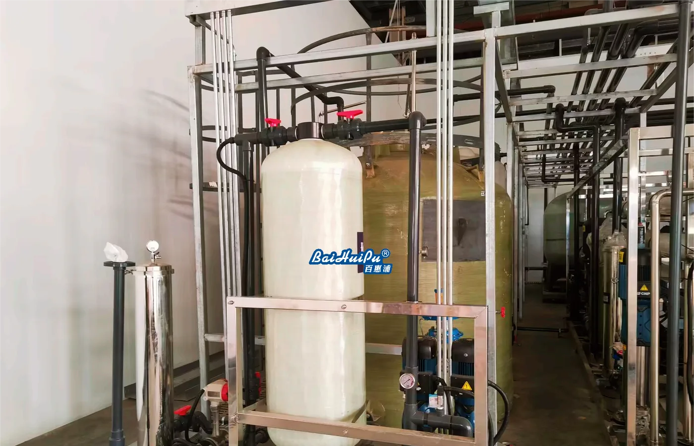
The featured photograph shows industrial water-treatment equipment and tanks as context; it does not identify a particular radar transmitter or prove measurement performance. Use the offered instrument documentation, as-installed dimensions and commissioning records for acceptance. The linked storage and PLC articles address adjacent duties. Keeping geometry, signal scaling and validity explicit makes a continuous level measurement useful without assuming that a catalogue technology claim establishes every inventory, control or protective function at the site.
Questions buyers commonly ask
Does radar always measure through foam?+
Do not assume it. Describe the actual foam and surface conditions and obtain model-specific application review or trial evidence.
Is tank level always proportional to stored volume?+
No. Volume conversion depends on tank geometry and the correct reference or strapping data. Verify the variable used by each plant function.
Can the last valid level remain on the screen?+
It can be displayed with clear validity and age information. Define how stale data affects automatic filling and pumping decisions.
What should commissioning retain?+
Save mounting dimensions, range and datum, relevant echo diagnostics, reference checks, controller scaling and demonstrated fault and recovery responses.
Turn the guide into a project brief.
Final process selection and performance commitments should follow the complete feed-water analysis, application requirements, site utilities and approved technical agreement.