The RO permeate connection needs a hydraulic and control review, particularly when multiple trains share a header or supply pressurized downstream equipment. Define allowable conditions with the selected membrane supplier and examine shutdown states before approving valves and site interfaces.
Establish the membrane-specific pressure basis
Obtain the selected membrane manufacturer's requirements for permeate pressure, relevant differential conditions and operation during transitions. Keep element limits separate from vessel and pipe ratings. A pressure vessel can satisfy its mechanical design while the membrane inside experiences an unsuitable hydraulic condition. Do not apply an assumed universal allowance across different elements or process arrangements. The procurement documents should identify the approved manufacturer basis and the party responsible for checking the connected installation against it.
Distinguish normal pressurized permeate operation, where specifically designed and allowed, from an unreviewed reverse pressure condition. DuPont guidance addresses permeate backpressure and describes damage associated with unsuitable conditions. That supports a focused interface review, not a blanket claim that every positive permeate pressure is prohibited or that one familiar limit applies universally. Request the relevant documentation for the actual system and preserve it with the final hydraulic and control design.
Draw the complete permeate-side connection
Trace permeate from every vessel through collection headers, quality diversion, storage and downstream equipment. Include elevation, check valves, isolation valves and any pump that can influence the line. Show the pressure boundary when destination storage is full or an outlet valve is closed. A drawing that ends at the skid connection cannot establish the condition created by external site piping. Assign ownership of that interface explicitly between the RO supplier and site integrator.
Identify other water sources that connect to the same header, including parallel RO trains, flushing water and downstream recirculation arrangements. Review whether pressure from one source can reach an isolated or depressurized train. Do not assume that identical nominal pipe pressure means the hydraulic states are equivalent. Mark the actual flow paths for normal production, standby and maintenance so a reviewer can see which physical barrier or sequence establishes the intended separation in each state.
Send the feed-water analysis, target quality, required capacity and operating profile. We will help structure the next engineering questions.
Send your project inputsExamine shutdown as a distinct condition
Walk through controlled shutdown and unexpected power loss using the actual feed, concentrate and permeate arrangement. Track how pressures change and which valves move, remain open or fail to another position. A system that is acceptable during stable production may reach a different differential condition as feed pressure falls. Ask the responsible engineer to assess this transition with the equipment suppliers rather than assuming a normal operating pressure reading covers the event.
Include downstream equipment that can remain pressurized after the RO train stops. Identify stored hydraulic energy, elevation head and connected pumps where relevant. Review how long any pressure can persist and how the design establishes an acceptable state. Keep shutdown protection distinct from long-term membrane preservation procedures. Both belong in a complete operating plan, but a preservation chemical instruction does not demonstrate that the immediate hydraulic transition has been engineered correctly.
Review shared-header operation and isolation
Assess combinations of operating, standby and unavailable trains. A common header can expose a stopped train to conditions generated by another train that remains in duty. Define the intended isolation and pressure management for each combination. Ask the supplier to explain how the arrangement remains suitable at low production as well as maximum simultaneous flow. The design should not depend on an undocumented operator action every time one train changes state.
Review valve leakage and maintenance assumptions with the selected manufacturers and the responsible process engineer. A component intended to reduce reverse flow may not provide every isolation function the operating procedure requires. Identify any inspection or confirmation needed before a train is opened or returned to service. Keep personnel isolation arrangements under the site's approved procedures. The procurement review should describe the hydraulic protection function precisely rather than using one generic valve symbol to imply all necessary barriers.
Coordinate diversion and flushing connections
Show where off-spec permeate is diverted and what pressure exists at that destination. Review the normal and failed positions of diversion and outlet valves. Include conditions in which one path closes before another becomes available. A quality-control sequence must also preserve acceptable hydraulics. Ask the automation and process teams to approve the same cause-and-effect document so a change intended to protect water quality does not introduce an unreviewed pressure condition on the membrane side.
Trace flushing supply and drain routes, including any external pump or pressurized water connection. Obtain the selected membrane supplier's approved flushing requirements and verify that the arrangement can meet them. Avoid assuming that available plant water is automatically suitable or that a flushing connection can be used independently of valve state. Define permissions and confirmations for the actual installation, with practical operator information when the sequence cannot establish the intended path.
Select measurements and response logic
Identify pressure measurements needed to demonstrate compliance with the chosen equipment basis. Specify locations that represent the relevant membrane conditions and distinguish gauge pressure from the differential being evaluated. Ask whether available instrument response can resolve the transition of concern. A general plant pressure trend may support routine operation without proving a rapid event. Define the evidence required with the responsible engineer before choosing acceptance instruments or declaring a transient condition verified.
Write the response to failed measurements, unavailable valves and interrupted sequences. Determine whether the design relies on passive hydraulic features, active controls or a justified combination. State what each function actually protects and how its availability is confirmed. Avoid presenting a software interlock as sufficient without reviewing utility loss and physical device behaviour. The final narrative should explain how the system reaches an acceptable condition even when a normal command cannot be completed.
Verify the installed boundary and changes
Inspect valve types, orientation, connection elevations and pressure interfaces against approved drawings. Confirm that site changes have not introduced a pressurized destination or another connected source omitted from the review. Test relevant control states under an approved commissioning plan and record the actual conditions demonstrated. Do not improvise a damaging pressure event to prove a protection device. Use supplier-supported checks and justified analysis to establish the intended protection without exceeding equipment limits.
Retain the membrane requirements, hydraulic review, final sequences and acceptance records together. Identify modifications that require reassessment, such as a new downstream pump, changed storage elevation or additional parallel train. A small site piping alteration can change the permeate boundary even when the RO skid itself remains untouched. Give operations a clear document reference for future reviews so the original protection assumptions are not lost after the commissioning team leaves.
Prepare the permeate-interface enquiry
Send Baihuipu the selected membrane information, full permeate piping diagram, downstream pressures and operating sequence. Include shared sources, valve data, tank elevations and expected power-loss behaviour. Request an explicit interface review and a documented protection basis within the quotation. Use the related vessel guide for equipment connections and the shutdown-preservation guide for layup requirements, while keeping this hydraulic review focused on pressures and flow paths during connected operating states.
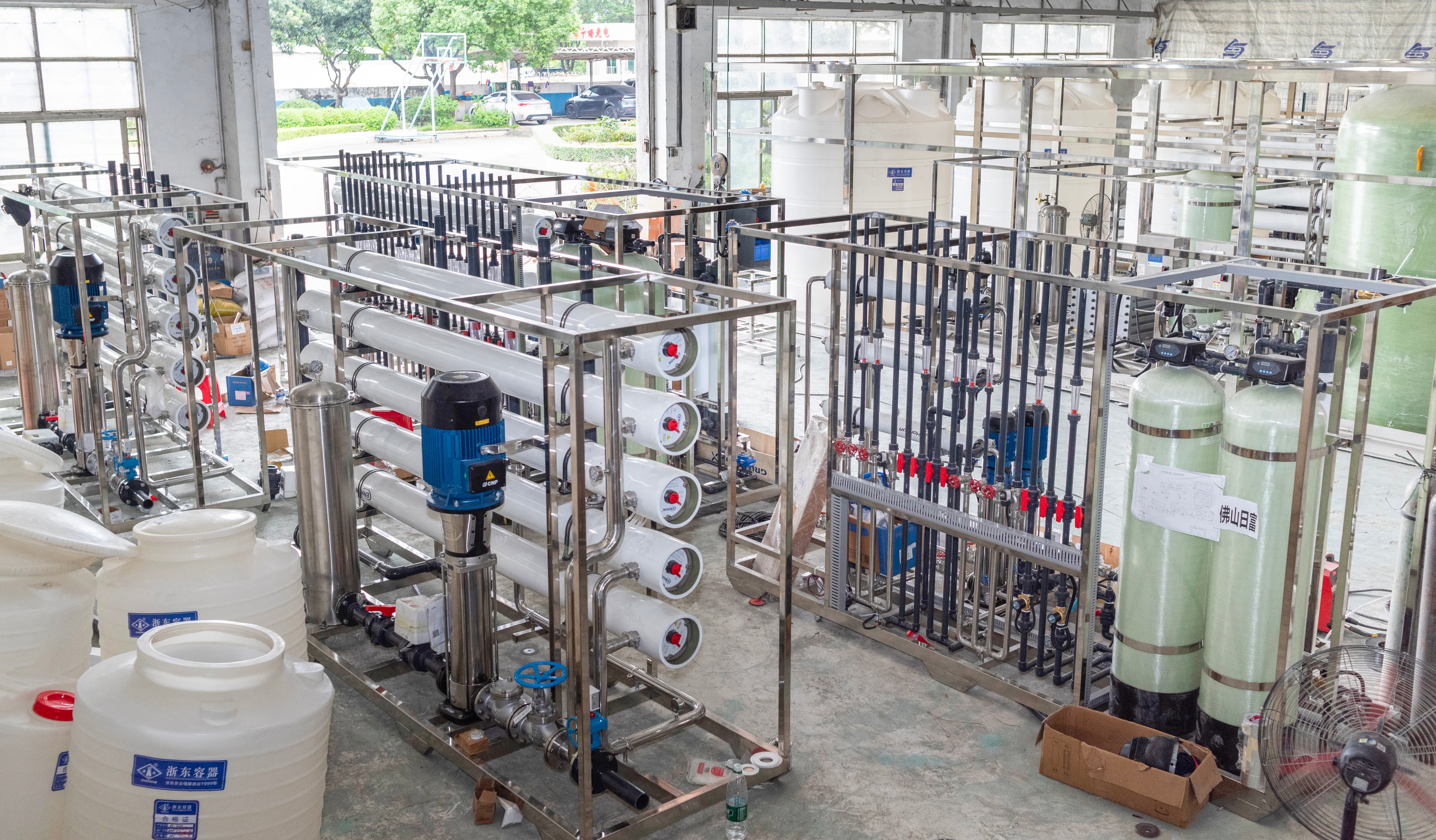
The photograph shows an industrial RO membrane train as context; it does not document pressure testing or prove backpressure protection. Confirm the actual offered arrangement through manufacturer requirements and approved engineering records. A complete purchase makes the permeate connection as reviewable as the feed connection. That helps the owner assess what happens when another train runs, a valve changes state or production stops, instead of discovering the interface only during an upset.
Questions buyers commonly ask
Does vessel pressure rating establish membrane backpressure tolerance?+
No. Obtain the selected membrane limits and evaluate the relevant hydraulic differential separately.
Can a stopped RO train be influenced by a common header?+
Yes, depending on the connected sources and protection arrangement. Review every operating combination.
Is permeate backpressure always prohibited?+
Use the selected manufacturer and application requirements. Approved pressurized operation and unsuitable reverse conditions are different cases.
When should the permeate review be repeated?+
Reassess changes to connected pumps, valves, storage elevations, parallel trains or control sequences that alter the boundary.
Turn the guide into a project brief.
Final process selection and performance commitments should follow the complete feed-water analysis, application requirements, site utilities and approved technical agreement.