A hydrocyclone or centrifugal separator should be selected from particle behaviour and a defined hydraulic range. It can be a useful grit-removal stage, but a nominal connection size or a clear-water test cannot establish performance on mixed industrial solids.
Establish whether the particles are separable
Identify the solids the package must remove and the reason for removing them. Sand, metal fines, light biological material and emulsified droplets do not behave identically. Collect particle-size information where useful, but pair it with material identity and density evidence. A size distribution alone can conceal particles that follow the water rather than separating. Record liquid temperature and composition because viscosity and density affect the separation environment.
LAKOS selection information identifies flow range, particle specific gravity and liquid viscosity as relevant considerations for its separators. Use those factors as questions for the offered design, without transferring a manufacturer's published performance to another package. Ask the vendor which feed fractions it expects to remove and which will remain. Define the downstream protection objective so the purchase is based on a measurable process need rather than a general promise of cleaner water.
Distinguish equipment types and outlet duties
Clarify whether the offered separator collects solids in a chamber for periodic purge or continuously splits flow into overflow and underflow. These arrangements have different water-loss and downstream-handling implications. Request a section drawing and marked flow paths. Suppliers sometimes use broad centrifugal-separation terminology for products with different internal geometry, so evaluate the actual offered mechanism rather than assuming that equipment names make quotations directly comparable.
Describe the acceptable separated-solids stream and the intended water outlet. A concentrated underflow sent to another process needs a different interface from grit dumped into a collection pot. Specify whether downstream equipment can tolerate remaining fine particles. Where a later filter is still required, include its loading in the system comparison. Removing a coarse fraction can be useful even when the separator is not the final barrier, provided that its limited role is explicit.
Send the feed-water analysis, target quality, required capacity and operating profile. We will help structure the next engineering questions.
Send your project inputsSelect around the full operating flow range
Provide minimum, normal and maximum flows at the separator during each production state. Include pump turndown, parallel train operation and intermittent users. An oversized separator can operate outside its useful range during routine low demand. Ask the vendor to show the intended hydraulic envelope and how multiple units are staged. A connection that fits the pipe does not establish that the internal velocities suit the actual separation duty.
Review pressure loss against the available pumping head, including fouled or abnormal downstream conditions. Identify where pressure readings will be taken and whether they can diagnose a change in flow. If the system uses a bypass or balancing valve, document the approved positions and commissioning method. Consider what happens when one parallel unit is isolated: the remaining units must stay within their allowable hydraulic conditions instead of receiving an uncontrolled share of the flow.
Run a test that measures both outlets
Use representative solids and operating liquid rather than a substitute selected for convenience. Record inlet conditions, flow and relevant pressures with the test results. Compare particle or solids concentrations on a consistent analytical basis. If an underflow or purge stream is produced, measure its flow and composition as well. Without this information, a seemingly improved water outlet may conceal a high water loss or an incomplete solids balance.
Define sampling locations that avoid collecting only the easiest material to capture. Settled grit in a sample hose can distort the apparent inlet and outlet difference. Ask how samples remain representative during an intermittent purge. Retain raw data and state the operating conditions that the test covers. Where performance varies across particle classes, require that distribution rather than a single removal percentage that could mask poor capture of the fraction important to the process.
Engineer solids collection and purge
Estimate the incoming solids load from measured concentration and flow, then agree how often the collection space must be emptied. Show the purge valve, line size, receiving container and isolation points on the drawing. The outlet needs to pass the expected grit without recurring blockage. Consider abrasion and the possibility of compacted solids after an extended pause. A small automatic valve does not create a reliable purge route by itself.
Check drain pressure and elevation, including the condition when a shared receiving tank is nearly full. If purge depends on available hydraulic pressure, demonstrate that condition at minimum operating flow. Define how the controller detects an unsuccessful purge and how operators inspect the route. Include the water carried with solids in operating cost and water balance comparisons. For continuous underflow equipment, make its downstream collection or dewatering duty equally explicit in the purchase boundary.
Review abrasion, corrosion and maintenance
Match body, liner, seals and collection components to liquid chemistry and the abrasive character of the solids. Discuss wear at high-velocity regions and ask how replacement parts are inspected and changed. A corrosion-resistant material can still be vulnerable to erosion. Request the offered supplier's limits and evidence for the combined duty rather than relying on a general material label. Include temperature and cleaning exposures in the compatibility review.
Reserve access for collection-chamber inspection and removal of internals where applicable. Provide a safe method to isolate, depressurize and drain the unit before opening it. Confirm supports and nozzle loads so adjacent pipework does not distort the housing. Compare spare liners, seals and valves across quotations. Where the process runs continuously, identify how water quality is protected during maintenance and whether a standby separator or another temporary route is required.
Integrate without confusing solids and chemistry
A separator can remove suitable particles but does not replace scale control, dissolved-salt removal or biological management. Review how chemical addition changes the solids presented to it. If upstream treatment creates fragile floc, a high-shear transfer or separation stage may alter that floc and deserve testing. Keep any credit for reduced downstream load tied to evidence from the actual combined arrangement rather than adding equipment-stage claims arithmetically.
Specify operating responses to low flow, excessive pressure loss, failed purge and an unavailable receiving container. Record a normal baseline after commissioning so operators can distinguish a change in source water from a change in hydraulics. Where sampling is needed, provide accessible points on both water and solids routes. The resulting operating plan should tell staff when the separator remains useful and when continued operation risks passing the unwanted grit downstream.
Prepare a centrifugal-separator enquiry
Send Baihuipu the particle description, concentration range, liquid properties, operating flow profile, available head and solids destination. Request an offer that identifies the equipment mechanism, predicted separation envelope, purge requirement and trial limitations. Agree acceptance for the important particle fraction and the installed hydraulic states. Include purge completion and safe maintenance access in the demonstration, because water-side performance alone does not establish a usable separation package.
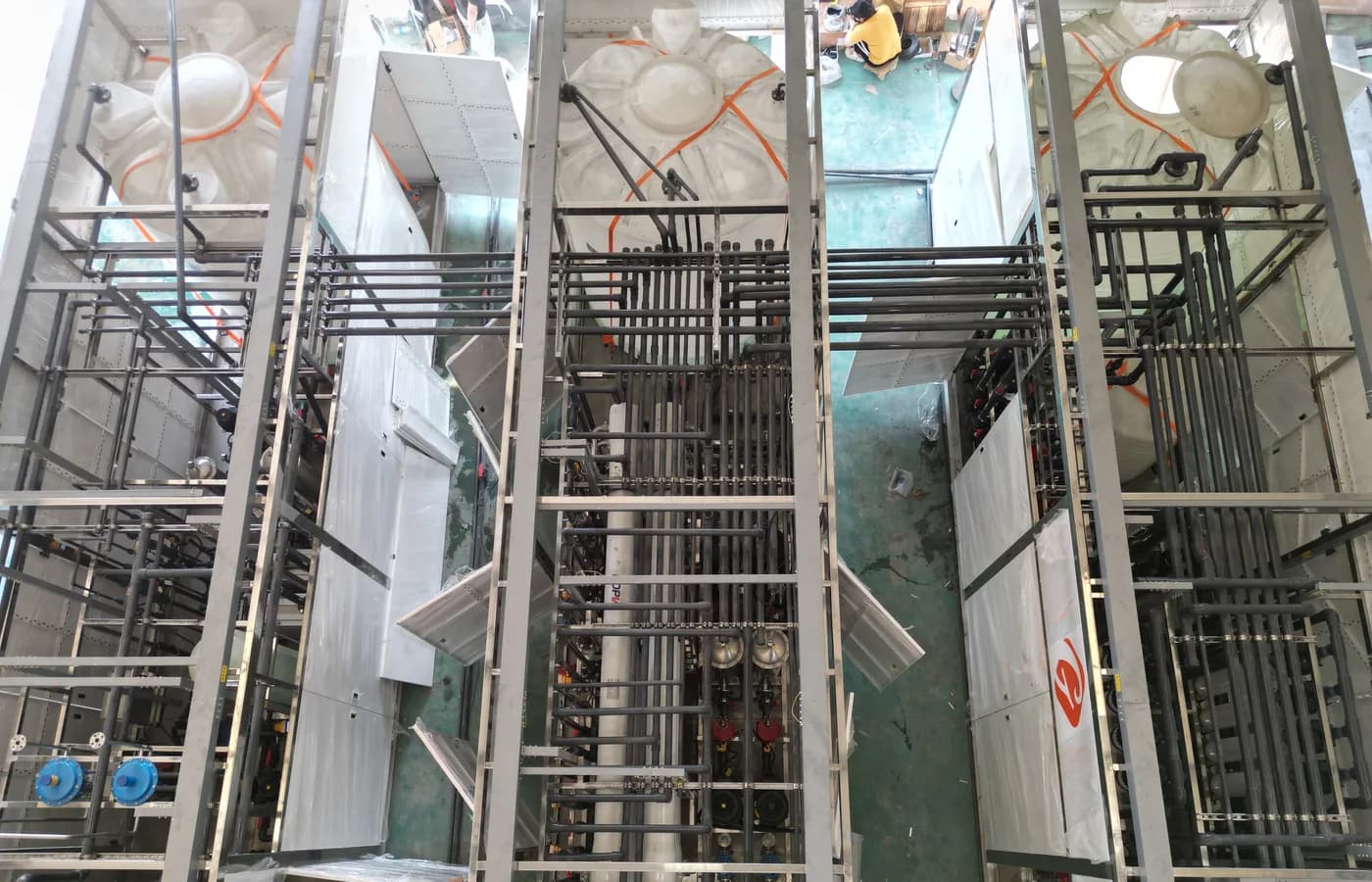
The image depicts industrial treatment piping and equipment as context; it is not a hydrocyclone identification or a test record. Use the actual proposed drawings, solids evidence and witnessed observations when judging suitability. The linked settling and coalescing guides cover different separation mechanisms. Comparing them is valuable only when each is evaluated against the same source stream and receiving-process requirement, with all reject flows and remaining treatment duties included.
Questions buyers commonly ask
Can a hydrocyclone remove every suspended particle?+
No. Separation depends on the offered geometry, operating hydraulics and particle properties. Establish performance for the fraction relevant to the protected process.
Why can oversizing reduce usefulness?+
A unit selected only for maximum flow may run outside its intended hydraulic range during low demand. Review staging and turndown with the supplier.
Is a grit separator a dissolved-salt treatment stage?+
No. Dissolved contaminants require a separate process selected from the water analysis. Do not credit particle separation with desalination.
What should a purge acceptance test demonstrate?+
Show actual solids withdrawal, a clear receiving route, acceptable water loss and a defined response when a valve or drain does not work.
Turn the guide into a project brief.
Final process selection and performance commitments should follow the complete feed-water analysis, application requirements, site utilities and approved technical agreement.